NodeMCU deepSleep Fehler vermeiden

NodeMCU

Während meiner Versuche mit dem NodeMCU und deepSleep stieß ich auf zwei Fehler die man machen kann, aber nicht sollte. Der erste lies mich den Baustein nicht mehr mit neuem Code bespielen. Der Grund ist, dass der Baustein während er im deepSleep Mode ist, sich nicht mehr flashen lässt. Die Lösung des Problems ist hier beschrieben:

Solution: https://forum.arduino.cc/index.php?topic=613412.0

You do not say what version of ESP8266 your using but if it has two buttons on the module (maybe called Reset & Flash) then hold down the flash button, briefly press the reset button and then after a second or two release the flash button. This should put the ESP into programming mode where the built in bootloader is running instead of your sketch.

Is there any other method putting the Wemos into programming mode instead of the second (flash) button?
Connect GPIO0 (that I think is pin D3 on the D1 Mini) to GND and then press the reset button.
You may also need to remove the D0-RST link but I’m not sure.

Der andere schwierig zu findende Fehler war, (vor lauter Begeisterung vergessen 😉 ) abzufangen, falls mal keine Verbindung zustande kommt. Hier ganz einfach mit dem Zähler tries behoben. Ansonsten geht er in Endlosschleife …

//connect to your local wi-fi network
WiFi.begin(ssid, password);/check wi-fi is connected to wi-fi network
int tries = 0;
while (WiFi.status() != WL_CONNECTED) {
delay(1000);
Serial.print(".");
tries++;
if (tries > 10) {
// wenn keine verbindung gelingt
Serial.println("No WiFi! Gonig to Sleep");
ESP.deepSleep(10e7);
}}
Serial.println("");
Serial.println("WiFi connected..!");
Serial.print("Got IP: "); Serial.println(WiFi.localIP());

Arduino mirror image, orientation problem with display MAX7219

How to use MAX7219 LED Matrix with Arduino

Good Libraries to use with the MAX7219 LED are:
https://github.com/MajicDesigns/MD_MAX72XX LED
https://github.com/MajicDesigns/MD_Parola Scrolling

You’ll find lot’s of examples after you install the libraries in the Arduino IDE.

Arduino mirror image, orientation problem with display MAX7219

How to solve problem with the LED matrix MAX7219 and the MD_MAX72xx.h Library

If you have problems with mirroring and/or orientation find following line and try following solutions, Choose one:

#define HARDWARE_TYPE MD_MAX72XX::FC16_HW


#define HARDWARE_TYPE MD_MAX72XX::PAROLA_HW


#define HARDWARE_TYPE MD_MAX72XX::GENERIC_HW


#define HARDWARE_TYPE MD_MAX72XX::ICSTATION_HW

Günstig Temperatur, Luftfeuchte und Energie messen mit Raspberry Pi oder PC

Drahtloses Anbinden von Temperatursensoren und Energiemesser. Und das noch günstig. Sehr hilfreich war dieser Beitrag. Er beschreibt die Anbindung von drahtlosen Sensoren an Fhem. Fhem wollte ich jetzt (noch) nicht aufsetzen, deshalb realisierte ich meine eigene Anbindung in der die Temperaturkurven auf dem Webserver des Raspi angezeigt werden.Bildschirmfoto 2014-03-19 um 21.28.26

Zutaten: Ein Raspi (kann aber auch ein NAS, PC oder Mac sein). Ein Jeelink (arduino mit 868 MHz Sender/Empfänger auf einem USB-Stick) (Versand dauert ca. 4 Tage). Einen (oder mehrere, ich habe inzwischen 7) passende Temperatursensoren. (Gibt es auch mit Luftfeuchtemesser).

Verarbeitung: Der Jeelink muss mit dem passenden Sketch bestückt werden. Danach lauscht er nach senden Thermostationen und gibt das Ergebnis über seine serielle Schnittstelle aus. Zum Auslesen habe ich mir folgendes Perl-Script erstellt (alpha):

#!/usr/bin/perl
$|++;

# LaCrosse auslesen
# Interpretation:
# OK
# 9
# 1 Byte: addr
# 1 Byte: battery, type, channel
# 2 Byte: temperature 
# 1 Byte: battery_low, humidity

use strict;
use warnings;

use Device::SerialPort;

my $device1 = 'F0'; 
my $device2 = '68'; 
my $device3 = 'E0'; 
my $device4 = 'CC'; 
my $device5 = '58'; 
my $device6 = 'D4'; # Fensterbrett war 38
my $device7 = '54'; 
my $device8 = 'DC'; 
my $device9 = '94'; 

my $port;
my %devices = ($device1 => 'n', $device2 => 'n', $device3 => 'n', $device4 => 'n', $device5 => 'n', $device6 => 'n', $device7 => 'n', $device8 => 'n', $device9 => 'n');
	my $sec;
	my $min;
	my $hour;
	my $mday;
	my $mon;
	my $year;
	my $wday;
	my $yday;
	my $isdst;
	my @myvalues;
	my $hygro;

 sub check_output{

     my $answer;
     my $answer1;
     # my( @bytes, $channel,$cmd,$addr,$data,$power,$consumption );
     my( @bytes, $addr, $battery_new, $type, $channel, $temperature, $battery_low, $humidity ); 
      my $state;
      my $readonly;

	my @array;
	my $len;

 while(1){    
	print STDERR "wait for read\n";
    $answer1 = $port->read(255);
   	print STDERR "\n>" . $answer1 . "<-\n";

	#print "read\n";
    if ($answer1 ne "") {
    	$answer = $answer . $answer1;
    	#print "\n>" . $answer . "<\n";
		if( $answer =~ m/^OK.*\n/ ) {
			last;
		}
		$len = length($answer);    	
		if ($answer ne "" && $len > 1000){ #something went wrong
			print STDERR "---- delete length $len too long----\n";
			print STDERR ">" . $answer . "<\n";
			$answer = "";
			}
		if (length($answer) >= 2){
			if (substr($answer, 0, 2) ne "OK"){ #something went wrong
				print  STDERR  "---- delete wrong start----\n";
				$answer = "";
				}
			}

    }
    sleep(2);
}
#Falls mehrere Zeilen geliefert werden, 
@array=split(/\n/, $answer);

foreach (@array){
$answer = $_;
#  if( $answer =~ m/^OK.*\n/ ) {
  if( $answer =~ m/OK 9 \d+ \d+ \d+ \d+ \d+/ ) {
    @bytes = split( ' ', substr($answer, 5) );

 $addr = sprintf( "%02X", $bytes[0] );
$battery_new = ($bytes[1] & 0x80) >> 7;
$type = ($bytes[1] & 0x70) >> 4;
$channel = $bytes[1] & 0x0F;
$temperature = ($bytes[2]*256 + $bytes[3] - 1000)/10;
$battery_low = ($bytes[4] & 0x80) >> 7;
$humidity = $bytes[4] & 0x7f; 

 # we simply write the temperatur at the hash
	print STDERR "Adr: " . $addr;
    print STDERR " Batt_new: " . $battery_new;
    print STDERR " Type: " . $type;
    print STDERR " Chan: " . $channel;
    print STDERR " Temp: " . $temperature;
    print STDERR " Batt_low: " . $battery_low;
    print STDERR " Hum: " . $humidity . "\n";
  $devices{$addr} = $temperature;
  if ($addr eq 'E0'){
  	$hygro = $humidity;
  }

  #Wenn neue Adresse, dann hier ausgeben

    $answer ="";

} 

 }#for each
}  # sub check_output

# -------------
# Hauptprogramm

    # Set up the serial port
    #print "Start\n";

    $port = Device::SerialPort->new("/dev/ttyUSB0");
#    $port = Device::SerialPort->new("/dev/tty.usbserial-AM01YRW0");

    # 19200, 81N on the USB ftdi driver
    $port->baudrate(57600); # you may change this value
    $port->databits(8); # but not this and the two following
    $port->parity("none");
    $port->stopbits(1);
    $port-> write_settings;
    $port-> lookclear;
     #print "start";

my $i;
$i = 7;        
while($i > 0){    

print STDERR "Durchlauf Nr: $i \n";

$port-> lookclear;
sleep(4);
check_output();

$i = $i -1;

#sleep(900);
#exit;

#debug

 # output block; put at the end
    ($sec,$min,$hour,$mday,$mon,$year,$wday,$yday,$isdst) = localtime();
    $mon = $mon +1;
    $mon = sprintf("%02d", $mon);
    $mday = sprintf("%02d", $mday);
    $hour = sprintf("%02d", $hour);
    $min = sprintf("%02d", $min);
    $sec = sprintf("%02d", $sec);
    $year = $year + 1900;
	#@myvalues = values %devices;

# ToDo Aufräumen, muss auch weiterlaufen wenn bei einem Gerät die Batterie leer ist	
if  ($devices{$device1} eq "n") {
 print STDERR "na 1  $device1 nicht gefunden\n";
 sleep(4);
 next;
}
if  ($devices{$device2} eq "n") {
 print STDERR "na 2  $device2 nicht gefunden\n";
 sleep(4);
 next;
}
if  ($devices{$device3} eq "n") {
 print STDERR "na 3  $device3 nicht gefunden\n";
 sleep(4);
 next;
}
if  ($devices{$device4} eq "n") {
 print STDERR "na 4  $device4 nicht gefunden\n";
 sleep(4);
 next;
}
if  ($devices{$device5} eq "n") {
 print STDERR "na 5  $device5 nicht gefunden\n";
 sleep(4);
 next;
}
if  ($devices{$device6} eq "n") {
 print STDERR "na 6  $device6 nicht gefunden\n";
 sleep(4);
 next;
}
if  ($devices{$device7} eq "n") {
 print STDERR "na 7 $device7 nicht gefunden\n";
 sleep(4);
 next;
}
if  ($devices{$device7} eq "n") {
 print STDERR "na 8 $device8 nicht gefunden\n";
 sleep(4);
 next;
}
if  ($devices{$device9} eq "n") {
 print STDERR "na 9 $device9 nicht gefunden\n";
 sleep(4);
 next;
}
	print "$year-$mon-$mday" . "_" . "$hour:$min:$sec";
	print " $devices{$device1}";
	print " $devices{$device2}";
	print " $devices{$device3}";
	print " $hygro";
	print " $devices{$device4}";
	print " $devices{$device5}";
	print " $devices{$device6}";
	print " $devices{$device7}";
	print " $devices{$device8}";
	print " $devices{$device9}";
	print "\n";
 # output block; put at the end

 #nochmal alle aufzaehlen
 print STDERR "Alle erfolgreich gefunden\n";

exit;

$i = $i -1;
sleep(58);
     #print "slept";

 }
    print STDERR "Abbruch nicht genug gefunden\n";
 	print "$year-$mon-$mday" . "_" . "$hour:$min:$sec";
	print " $devices{$device1}";
	print " $devices{$device2}";
	print " $devices{$device3}";
	print " $hygro";
	print " $devices{$device4}";
	print " $devices{$device5}";
	print " $devices{$device6}";
	print " $devices{$device7}";
	print " $devices{$device8}";
	print " $devices{$device9}";
	print "\n";

Dazu noch einen cronjob, der die ausgabe des Perl-scripts parst durch gnuplot schickt und die entstandene Grafikdatei auf den Webserver schiebt. – Fertig.

Detaillierend zu Sebastians Frage:

Die Ausgabedatei sieht z.B. ungefähr so aus (Pro Zeile Datum, Uhrzeit, dann die Werte mit blank getrennt n wenn kein Wert).:

2020-08-18_02:21:17 33.7 n 24.8 61 n -19 n 11.5 21.7 25.4 22 80 23.5 76 25.5 64 25.4 63 17.4 n 26.5 25.2 25.5 26 26 23.1 71 24.2 66 24.4 61
2020-08-18_02:31:18 33.7 n 24.8 61 n -18.9 n 11.4 21.6 25.4 22 79 23.5 76 25.5 64 n n 17.4 n 26.5 25.2 25.5 26 25.9 23.1 71 24.1 66 24.4 61
2020-08-18_02:41:14 33.7 n 24.8 61 n -19 n 11.4 21.6 25.4 22 79 23.5 76 25.5 64 25.4 63 17.2 n 26.4 25.2 25.5 26 25.9 23.1 71 24.1 66 24.4 61
2020-08-18_02:51:18 33.7 n 24.8 61 n -18.9 n 11.4 21.6 25.4 22 79 23.5 76 25.5 64 25.4 63 17.2 n 26.4 25.2 25.4 26 25.9 23 71 24.1 66 24.3 60

Darauf kann mann dann den gnuplot loslassen mit dem Befehl “gnuplot datei”. Die Datei steuert den gnuplot und kann z.B. so aussehen:


set key left #legende nach links
set xtics rotate
set xdata time
set timefmt "%Y-%m-%d_%H:%M:%S"
set format x "%d. %Hh"
set grid
set title "Johannes Temp Small Monitor"
set ylabel "C"
set xlabel "\n1 hour interval"
set terminal gif small size 800, 440 transparent
set output "/home/pi/bin/tc2small.gif"

plot "/home/pi/bin/temperatureout.txt" using 1:6 title "Sensor 1" with lines,\
"/home/pi/bin/temperatureout.txt" using 1:8 title "Sensor2" with lines, \
"/home/pi/bin/w4.txt" using 1:2 title "OpenWeather" with lines, \
"/home/pi/bin/weatherout_wunder3.txt" using 1:2 title "Wunderground" with lines

die entstandene gif Datei schiebe ich dann mittels ftp auf den Webserver.

Mittlerweile schreibe ich parallel dazu die Daten in eine mysql Datenbank und erstelle mittels Grafana die Auswertung. Das schaut dann ca. so aus wie unten.


Wie verbindet man den Jeelink mit dem Raspberry PI: link

X-MAS Special – Was ein Geek alles braucht

X-MAS Special – Was ein Geek alles braucht

Weihnachten steht vor der Tür, deshalb heute ein Special was ein geek unbedingt braucht:

PC, Smartphone und Pad: Laufen als Grundausstattung, deshalb keine Deatillierung hier.

NAS (Network Attached Server):  Mit minimalen Stromverbrauch und einfacher Bedienung kann das mittlerweile (fast) jeder bedienen. Geliefert wird meist ein leeres Gehäuse, Festplatte(n) einbauen, ans Netz hängen, installieren und los geht’s. Was kann so ein NAS? Netzwerklaufwerke bereitstellen und Datensicherung ist der Grundumfang. Da ein Linux draufläuft und eine einfache Bedienoberfläche (über Browser) vorhanden ist hat man in Windeseile zusätzlich z.B. eine Homepage, ein Blog, ein Fotoverzeichnis, VPN oder einen WordPressblog eingerichtet. Bei Synology (welches ich habe) gibt es zusätzlich noch die Cloud Station, eine private DropBox. Die Hersteller unterscheiden sich vor allem durch die mitgelieferte Software -> wichtiger als Hardware Specs!

Raspberry PI: Scheckkartengroßer Mini PC. Das Betriebssystem, ein angepasstes Linux, liegt auf einer SD Karte. Vorteil: Durch Wechsel der SD-Karte hat man unterschiedliche Konfigurationen zur Hand. Die 2 gebräuchlichsten XMBC und Raspbian. Mit XMBC hat man ein Mediencenter zum Anschluss an den Heim TV. Raspbian ein (abgespecktes) Linux mit Fensteroberfläche, zum wilden UNIX testen, besser aber das ganze Remote zu steuern. Bei mir tut einer seinen Dienst als Flur Monitor mit Wetter und News Anzeige. Ein weiteres Projekt wäre der Selbstbau eines Internetradios.

Apple TV: Wer einfach Video on demand haben möchte, gönne sich ein Apple TV. Vieles geht auch mit dem Raspberry PI, aber einfacher und bequemer ist das Apple Teil. Wenn man sowies schon Produkte dieser Firma daheim hat, sowieso schon fast ein muss. Funktioniert einfach.

Arduino: Ein Microcontroller zum einfachen Basteln. Über USB angeschlossen ermöglicht er einfache Programmierung mittels c. Nach dem Herantasten mit ein paar Leuchtdioden kann man schnell größere Projekte realisieren. Wer keine Lust auf Löten hat, besorge sich ein Steckverbinder Set, z.B. Grove von Seedstudio.

Ferngelenkte Modelle: Die Zeiten des Selberbastelns vom Fernlenkmodellen geht vorbei. Populär sind RTR (ready to run) oder RTF (ready to fly) Modelle. Ich rate von den billig Produkten ab, da ist es Glücksache wenn man etwas gutes erwischt. Für Fahrzeuge ist z.B. Traxxas ein empfehlenswerter Hersteller bei Hubschraubern und Quadcopter empfehle ich Blade.

Unten stehen sind die tags verlinkt, wer mehr zu einem Thema wissen möchte. have fun.

Grove Tick Tock Shield Kit

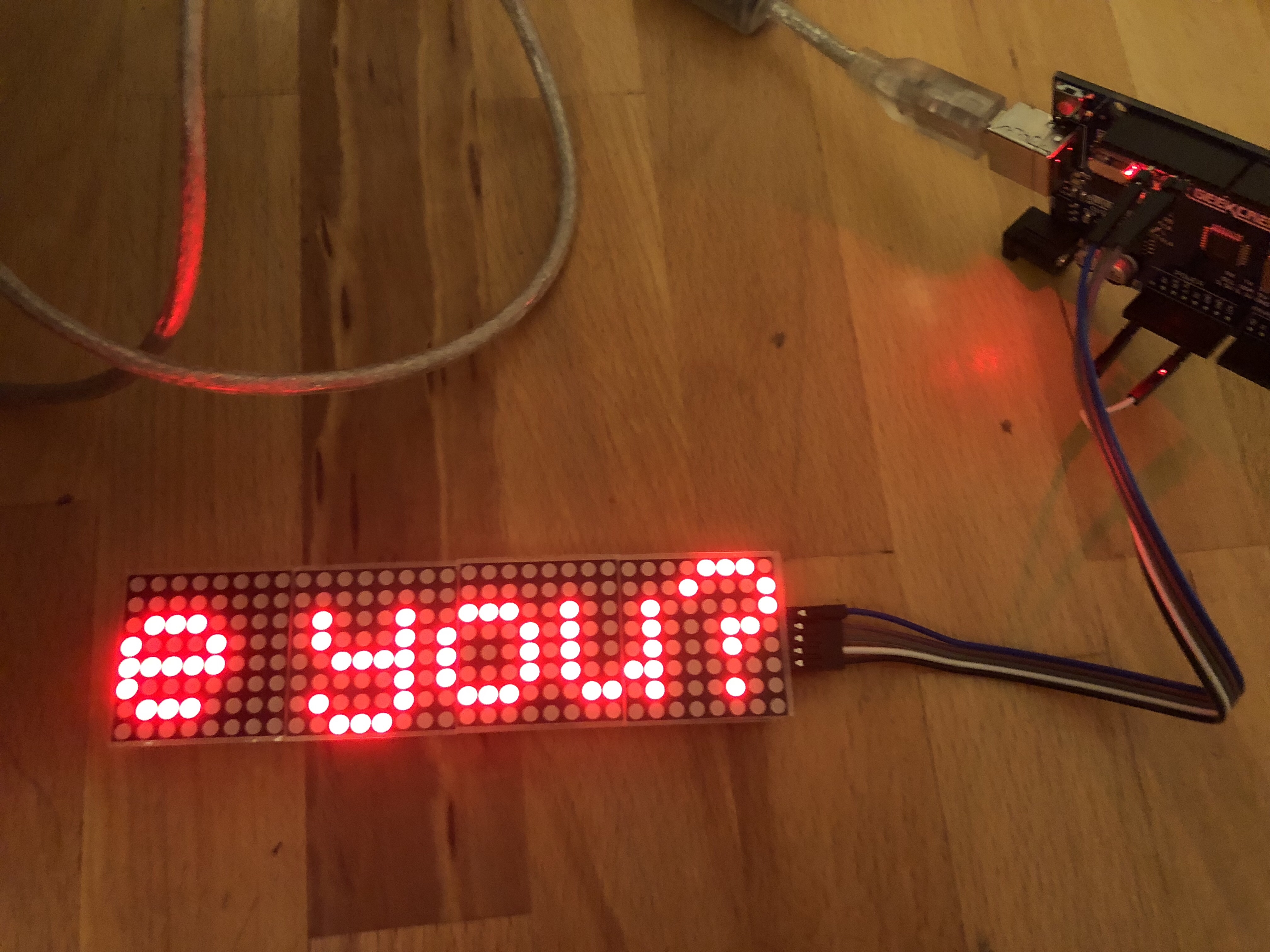
Giving the Tick Tock Shield Kit by Grove a try, I made same changes to the real time clock code. First I wanted to automaticaly change the brightness not only at the start of the code. And second I wanted the date to displayed to. Now it displays alternately with the temperature. (To set the date, do this once when hour and minutes are set, see comment there. This should be enough, no need to alter with the buttons). Had to change the library too. So find all the code here. RealTimeClock2:

/****************************************************************************/
//  Demo function:
//
//  Author:Frankie.Chu
//  Date:23 September, 2012
//
//  This library is free software; you can redistribute it and/or
//  modify it under the terms of the GNU Lesser General Public
//  License as published by the Free Software Foundation; either
//  version 2.1 of the License, or (at your option) any later version.
//
//  This library is distributed in the hope that it will be useful,
//  but WITHOUT ANY WARRANTY; without even the implied warranty of
//  MERCHANTABILITY or FITNESS FOR A PARTICULAR PURPOSE.  See the GNU
//  Lesser General Public License for more details.
//
//  You should have received a copy of the GNU Lesser General Public
//  License along with this library; if not, write to the Free Software
//  Foundation, Inc., 51 Franklin St, Fifth Floor, Boston, MA  02110-1301  USA
//
//  Modified record:
//  Johannes, added function for auto brighness and showing date 11/2013
//
/*******************************************************************************/

#include "Wire.h"
#include <TimerOne.h>
#include <MsTimer2.h>
#include <EEPROM.h>
#include "TM1636.h"
#include "TickTockShield.h"

#define ON 1
#define OFF 0

//definitions of global variables
boolean flag_update;//1 = update the time on the 4-digit display
unsigned char halfsecond;//each time the timer2 interrupts,halfsecond plus one.
boolean flag_clockpoint = 1;//change between 0 and 1 every 500ms. If it is 1,
//the clockpoint is on.Else the clockpoint is off.
boolean flag_2s;//2 seconds flag.1 = to the end of 2 seconds so as to set 
//flag_display_time
boolean flag_10s;//10 seconds flag.1 = to the end of 10 seconds so as to 
//display temperature
boolean flag_display_time = 1;//1 = can display time that get from the RTC
uint8_t counter_times = 20;//20*halfsecond = 10seconds.
//If it is 20,to count for 10s,so display time for 10s.
//If it is 4,to count for 2s,so display the temperture for 2s
boolean flag_500ms_blink;//when adjusting the time or the alarm,the hour or minute
//displayed on the 4-digit display will blink every 500ms.
boolean flag_scan_again;//1 = can scan key again at the state of SYSTEM_NORAML
//To avoid the mistake of entering the state of SYSTEM_ADJUSTING 
//again when pressing MENU for 3s to confirm the setting.
uint8_t counter_500ms;//when counter_500 reach 6,flag_scan_again is set 1.

boolean flag_temp_shown; // added by Johannes

/*status definitions for the tick shield control system*/
uint8_t system_states;
#define SYSTEM_NORAML    0 //default status,and the system will turn to "normal" status 
#define SYSTEM_ADJUSTING 1 //triggered when key MENU is pressed at the "normal" status.
#define SYSTEM_ALARMING  2

//--Declare a TickTockShield Class object--//
TickTockShield ticktockshield;

extern int8_t disp[4];//external global array defined in TickTockShield.cpp

extern byte g_hand;//external global variable.
//the clock hand, HOUR shows that it is adjusting the hour, 
//MINUTE shows that it is adjusting the minute.

void setup() 
{
#ifdef DEBUG
  Serial.begin(9600);
#endif
  ticktockshield.init();

  /*Run the 4 LEDs from left to right*/
  ticktockshield.runLED();
  if(isFirstLoad())//if it is the first time to load the firmware?
  {
    ticktockshield.setAlarm(12,0);//Yes,the alarm clock is initialized to 12:00
    //and the data in the EEPROM.
  }
  else ticktockshield.getAlarm();//No,read the alarm clock stored in EEPROM
  /*When system starts, adjust the brightness of the digital tube 
   			according to the ambient light intensity.*/
  uint8_t lightlevel; 
  lightlevel = ticktockshield.getLightLevel();
  ticktockshield.adjustBrightness(lightlevel);
  /*Read the ambient temperature and display on the digital tube.*/
  ticktockshield.displayTemperature(ticktockshield.getTemperature());
  delay(1000);
  MsTimer2::set(500, Timer2ISR);//Timer2 generates an interrupt every 500ms
  MsTimer2::start();//Timer2 starts counting
}
void loop() 
{
  clockStart();
}
/****************************************************************/
/*Function:Implement the function of a clock with an alarm clock, and */
/*			the buttons can adjust the clock.*/
void clockStart()
{
  if(system_states == SYSTEM_NORAML)//if it is normal states?
  {
    /*Yes, the clock will update every 500ms,and check whether the Menu is pressed */
    /*to enter SYSTEM_ADJUSTING state and check if it should be enter SYSTEM_ALARMING state.*/
    if(flag_update)//if update flag is not zero?
    { 
      flag_update = 0;
      if(flag_clockpoint)
      {
        tm1636.point(POINT_ON);
      }
      else tm1636.point(POINT_OFF); 
      ticktockshield.getTime();
      if(ticktockshield.isAlarmEnable())
      {
        tm1636.point(POINT_ON);
        ticktockshield.displayTime();
        system_states = SYSTEM_ALARMING;
        return;
      }
      if(flag_display_time)ticktockshield.displayTime();

      if(flag_2s)
      {
        flag_2s = 0;
        flag_display_time = 1;

        counter_times = 20;
        halfsecond = 0;
      }
      if(flag_10s)
      {
        flag_10s = 0;
        flag_display_time = 0;

        if(flag_temp_shown == 0){
          tm1636.point(POINT_OFF);
          ticktockshield.displayTemperature(ticktockshield.getTemperature());
          flag_temp_shown = 1;
        } 
        else {

          // Johannes: Set the new brightness; bug fixed 7 - lightlevel as parameter
          uint8_t lightlevel; 
          lightlevel = ticktockshield.getLightLevel();
          ticktockshield.adjustBrightness(7 - lightlevel);

          tm1636.point(POINT_ON);
          ticktockshield.displayDate(); 
          flag_temp_shown = 0;

        }

        counter_times = 4;
        halfsecond = 0;

        /*
        int8_t temp[4];
         temp[0] = ticktockshield.g_dayOfMonth/10;
         temp[1] = g_dayOfMonth%10;
         temp[2] = g_month/10;
         temp[3] = g_month%10;
         	tm1636.display(temp);
         */
      }
      if((flag_scan_again)&&(KEY_MENU == ticktockshield.scanKey()))
      {
        ticktockshield.writeToAdjustArea();
        ticktockshield.processKey();
        system_states = SYSTEM_ADJUSTING;
      }

    }
  }
  else if(system_states == SYSTEM_ADJUSTING)
  {
    ticktockshield.scanKey();
    ticktockshield.processKey();
    ticktockshield.processSystemStatus();
    if(ticktockshield.getQuitReq())
    {
      system_states = SYSTEM_NORAML;
      counter_500ms = 0;
      flag_scan_again = 0;
    }
    else flag_scan_again = 1;
  }
  else if(system_states == SYSTEM_ALARMING)
  {
    /*It will sound alarm for a minute untill the "MENU" key is pressed*/
    if(ticktockshield.isAlarmEnable())
    {
      ticktockshield.alarming();
    }
    else 
    {
      ticktockshield.turnOffAlarm();
      system_states = SYSTEM_NORAML;
    }
    if(KEY_MENU == ticktockshield.scanKey())
    {
      ticktockshield.turnOffAlarm();
      system_states = SYSTEM_NORAML;
    }
  }
}

//--------------------------------------
boolean isFirstLoad()
{
  unsigned char mark[] = "ALARM";
  unsigned char temp_data[5];
  for(unsigned char i = 0;i < 5;i ++)
  {
    temp_data[i] = EEPROM.read(i);
    if(temp_data[i] != mark[i])
    {
      EEPROM.write(0,mark[0]);
      EEPROM.write(1,mark[1]);
      EEPROM.write(2,mark[2]);
      EEPROM.write(3,mark[3]);
      EEPROM.write(4,mark[4]);
      return true;
    }
  }
  return false;
}

/*Function:It is timer 2 interrupt service routine.Timer2 generates an interrupt*/
/*  every 500ms.And every time it interrupts,this function will be executed.*/
void Timer2ISR()
{
  halfsecond ++;
  if(halfsecond  == counter_times)
  {
    halfsecond  = 0;
    if(counter_times == 4)flag_2s = 1;
    else if(counter_times == 20)flag_10s = 1;
  }
  flag_update = 1;
  flag_clockpoint = (~flag_clockpoint) & 0x01;//change between 0 and 1 every 500ms.
  flag_500ms_blink = ~flag_500ms_blink;
  if(ticktockshield.isAdjustingTime())
  {
    if(g_hand == HOUR)
    {
      if(flag_500ms_blink)
      {
        disp[0] = INDEX_BLANK;
        disp[1] = INDEX_BLANK;
      }
    }
    else
    {
      if(flag_500ms_blink)
      {
        disp[2] = INDEX_BLANK;
        disp[3] = INDEX_BLANK;
      }
    }
    tm1636.display(disp);
  }
  counter_500ms ++;
  if(counter_500ms == 6)
  {
    counter_500ms = 0;
    flag_scan_again = 1;
  }

}

TickTockShield.h:

#ifndef TICKTOCKSHIELD_H_
#define TICKTOCKSHIELD_H_

#include "TM1636.h"

#define DS1307_I2C_ADDRESS 0x68

//debug configuration
#define DEBUG 0
//-------pin definition of keys---------------//
#define KEY_MENU	11
#define KEY_UP		10
#define KEY_DOWN	9

//-------pin definition of LEDs---------------//
#define LED_CLOCK_ADJUST	5
#define LED_ALARM_ADJUST	4
#define LED_ALARM_ENABLE	3
#define LED_BRIGHT_ADJUST	2

#define ALARM_BUZZER		6

//-------pin definition of sensors-------------//
#define TEMPERATURE_SENSOR	A0
#define LIGHT_SENSOR		A1

#define LED_ON	1
#define LED_OFF 0

#define HOUR	0
#define MINUTE	1
/*Direction of the LEDs to run*/
#define LEFT_TO_RIGHT 0
#define RIGHT_TO_LEFT 1
//-------Status bit definition of the Status flag----//
/*volatile typedef enum{
  SS_NO_INPUT = 0,//no keys input
  SS_CLOCKH_ADJUST,//adjust the hour of the clock
  SS_CLOCKM_ADJUST,	//adjust the minute of the clock
  SS_ALARMH_ADJUST,	//adjust the hour of the alarm
  SS_ALARMM_ADJUST,	//adjust the minute of the alarm
  SS_ALARM_ENABLE,  //to enable or disable the alarm
  SS_BRIGHT_ADJUST,	//adjust the brightness of the 4-digit display
  SS_CONFIRM_EXIT,  //It will confirm the setting and exit after pressing the MENU button for more than 3s
  					//or after pressing it again at the status of adjust brightness.
  SS_QUIT,			//It will exit without saving any setting if no button is pressed within 5s.
}keyStatusType;*/
//extern keyStatusType system_status;

#define SS_NO_INPUT 		0//no keys input
#define SS_CLOCKH_ADJUST	1//adjust the hour of the clock
#define SS_CLOCKM_ADJUST	2//adjust the minute of the clock
#define SS_ALARMH_ADJUST	3//adjust the hour of the alarm
#define SS_ALARMM_ADJUST	4//adjust the minute of the alarm
#define SS_ALARM_ENABLE  	5//to enable or disable the alarm
#define SS_BRIGHT_ADJUST	6//adjust the brightness of the 4-digit display
#define SS_CONFIRM_EXIT  	7//It will confirm the setting and exit after pressing the MENU button for more than 3s
							 //or after pressing it again at the status of adjust brightness.
#define SS_QUIT				8//It will exit without saving any setting if no button is pressed within 5s.

#define KEY_PRESSED 1
#define KEY_RELEASE 2

#define RESISTOR_CONNECT_THERMISTOR	10000
struct AlarmStruct
{
  byte hour;
  byte minute;
  boolean flag_enable;
};
class TickTockShield
{
public:
  void init();
  void setLed(unsigned char led_status, int pinLED);
  void turnOffLED();
  void turnOnLED();
  void runLED(byte = 1, byte = LEFT_TO_RIGHT);
  int16_t scanKey();
  void processKey();
  void processSystemStatus();
  void quit();
  void saveChanges();
  inline void modifyAlarmFlag();
  void adjustClock(uint8_t hand);
  void adjustAlarm(uint8_t hand);
  void adjustBrightness();
  void adjustBrightness(uint8_t grayscale);
  int8_t getTemperature();
  void displayTemperature(int8_t temperature);
  float getLightIntensity();
  uint8_t getLightLevel();
  void ringOn();
  void ringOff();
  void alarming();
  void turnOffAlarm();
  boolean isAlarmEnable();
  boolean compareWithAlarm();
  inline void alarmDisable();
  void setAlarm(struct AlarmStruct alarm_);
  void setAlarm(uint8_t hour,uint8_t minute,uint8_t = 0);
  void getAlarm();

  void writeToAdjustArea();
  void writeToNormalArea();
  void writeTime();
  void getTime();
  void displayTime();
  void displayDate();  //added by Johannes
  void display(int8_t DispData []);
  void clearTime(uint8_t hand);
  byte decToBcd(byte val);
  byte bcdToDec(byte val);
  byte getQuitReq(){return flag_require_quit;}
  boolean isAdjustingTime();
private:
  /*Globle variables in the class*/
  byte g_second, g_minute, g_hour;
  /*when the clock is being adjusted, these two variables save the temporary data.*/
  byte g_minute_temp,g_hour_temp;
  byte g_dayOfWeek;
  byte g_dayOfMonth, g_month, g_year;
  AlarmStruct alarm;
  byte g_brightness;
  byte g_brightness_temp;
  /*when the alarm is being adjusted, this variable save the temporary data.*/
  AlarmStruct alarm_temp;
  int16_t pre_pin_number;//pin number of the key pressed before
  int16_t key_pin_pressed;//pin number of the key pressed now
  uint8_t tempKeyValue;
  uint8_t stateMenu;
  uint8_t stateUp;
  uint8_t stateDown;

  uint8_t system_status;
  byte flag_require_quit;
  boolean flag_adjust_time;
  boolean flag_alarm_over;

  void keyInit();
  void ledInit();
  void sensorInit();
  void buzzerInit();
};
extern TM1636 tm1636;

#endif

TickTockShield.cpp

#include "TickTockShield.h"
#include <Arduino.h>
#include <EEPROM.h>
#include <Wire.h>
#include <TimerOne.h>
#include "TM1636.h"

TM1636 tm1636(7,8);
void timerIsr();
/*global variables also used in timer interrupt serve routine */
uint8_t key_menu_status;
uint16_t count_10ms_pressed;
uint16_t count_10ms_release;
boolean flag_pressed_3s;
boolean flag_release_10s;
boolean alarm_on_off;

int8_t disp[4];
int8_t disp_buff[4];
byte g_hand;

//--------------------------------//
void TickTockShield::init()
{
	g_brightness = BRIGHT_TYPICAL;
  tm1636.set(g_brightness);
  tm1636.init();
  keyInit();
  ledInit();
  sensorInit();
	buzzerInit();
  Wire.begin();
	pre_pin_number = -1;
	Timer1.initialize(100000); // set a timer of length 100000 microseconds 
		//(or 0.1 sec - or 10Hz => the led will blink 5 times, 5 cycles of on-and-off, per second)
  Timer1.attachInterrupt( timerIsr ); // attach the service routine here
}

void TickTockShield::keyInit()
{
  //Set all three keys to be input and internal pull-up

  pinMode(KEY_MENU, INPUT);
  digitalWrite(KEY_MENU, HIGH);
  pinMode(KEY_UP, INPUT);
  digitalWrite(KEY_UP, HIGH);
  pinMode(KEY_DOWN, INPUT);
  digitalWrite(KEY_DOWN, HIGH);
}
void TickTockShield::ledInit()
{
  pinMode(LED_CLOCK_ADJUST, OUTPUT);
  pinMode(LED_ALARM_ADJUST, OUTPUT);
  pinMode(LED_BRIGHT_ADJUST, OUTPUT);
  pinMode(LED_ALARM_ENABLE, OUTPUT);
	turnOffLED();
}
void TickTockShield::sensorInit()
{
  pinMode(TEMPERATURE_SENSOR, INPUT);
  pinMode(LIGHT_SENSOR, INPUT);
}
void TickTockShield::buzzerInit()
{
	pinMode(ALARM_BUZZER, OUTPUT);
  pinMode(ALARM_BUZZER, OUTPUT);
}
void TickTockShield::setLed(unsigned char led_status, int pinLED)
{
	digitalWrite(pinLED, led_status);
}
/********************************/
void TickTockShield::turnOffLED()
{
	setLed(LOW,LED_CLOCK_ADJUST);
	setLed(LOW,LED_ALARM_ADJUST);
	setLed(LOW,LED_BRIGHT_ADJUST);
	setLed(LOW,LED_ALARM_ENABLE);
}
/********************************/
void TickTockShield::turnOnLED()
{
	setLed(HIGH,LED_CLOCK_ADJUST);
	setLed(HIGH,LED_ALARM_ADJUST);
	setLed(HIGH,LED_BRIGHT_ADJUST);
	setLed(HIGH,LED_ALARM_ENABLE);
}

/*******************************/
void TickTockShield::runLED(byte speed, byte direction)
{
	if((speed > 0)&&(speed < 11))//If the value of speed is valid?
	{
		turnOffLED();
		uint8_t shifter = 0x01;
		if(LEFT_TO_RIGHT == direction)
		{
			for(uint8_t i = 0;i < 4;i ++)
			{
				if(shifter&0x01) setLed(LED_ON,  LED_CLOCK_ADJUST);
				else						 setLed(LED_OFF, LED_CLOCK_ADJUST);
				if(shifter&0x02) setLed(LED_ON,  LED_ALARM_ADJUST);
				else					   setLed(LED_OFF, LED_ALARM_ADJUST);
				if(shifter&0x04) setLed(LED_ON,  LED_ALARM_ENABLE);
				else						 setLed(LED_OFF, LED_ALARM_ENABLE);
				if(shifter&0x08) setLed(LED_ON,  LED_BRIGHT_ADJUST);
				else						 setLed(LED_OFF, LED_BRIGHT_ADJUST);
				shifter <<= 1;
				delay(500/speed);
			}
		}
		else
		{
			for(uint8_t i = 0;i < 4;i ++)
			{
				if(shifter&0x01) setLed(LED_ON,  LED_BRIGHT_ADJUST);
				else						 setLed(LED_OFF, LED_BRIGHT_ADJUST);
				if(shifter&0x02) setLed(LED_ON,  LED_ALARM_ENABLE);
				else					   setLed(LED_OFF, LED_ALARM_ENABLE);
				if(shifter&0x04) setLed(LED_ON,  LED_ALARM_ADJUST);
				else						 setLed(LED_OFF, LED_ALARM_ADJUST);
				if(shifter&0x08) setLed(LED_ON,  LED_CLOCK_ADJUST);
				else						 setLed(LED_OFF, LED_CLOCK_ADJUST);
				shifter <<= 1;
				delay(500/speed);
			}
		}
		turnOffLED();
	}
}
//--------------------------------//
//-Return:the pin number of the key pressed
//--------------------------------//
//
int16_t TickTockShield::scanKey()
{
	int16_t pin_number = 0;
	static boolean pre_key_menu_level = HIGH;
	boolean cur_key_menu_level;
	if(digitalRead(KEY_MENU) == LOW)
	{
		delay(30);
		if(digitalRead(KEY_MENU) == LOW)
		{
			cur_key_menu_level = LOW;
			pin_number = KEY_MENU;
		}
		else cur_key_menu_level = HIGH;
	}
	else
	{
		cur_key_menu_level = HIGH;
	}
	if(pre_key_menu_level > cur_key_menu_level)
	{

		key_menu_status = KEY_PRESSED;
		if(system_status < 7)system_status ++;
		count_10ms_pressed = 0;
		flag_pressed_3s = 0;
	#ifdef DEBUG
		Serial.print("system_status = ");
	  Serial.println(system_status);
		Serial.println("Key_Menu pressed");
	#endif
	}
	else if(pre_key_menu_level < cur_key_menu_level)
	{
		key_menu_status = KEY_RELEASE;
		count_10ms_release = 0;
		flag_release_10s = 0;
	#ifdef DEBUG
		Serial.println("Key_Menu release");
  #endif
	}
	pre_key_menu_level = cur_key_menu_level;

	if(digitalRead(KEY_UP) == LOW)
	{
		delay(20);
		if(digitalRead(KEY_UP) == LOW)
		{
			pin_number = KEY_UP;
			count_10ms_release = 0;
			flag_release_10s = 0;
		#ifdef DEBUG
			Serial.println("Key_UP pressed");
		#endif
		}

	}
	else if(digitalRead(KEY_DOWN) == LOW)
	{
		delay(20);
		if(digitalRead(KEY_DOWN) == LOW)
		{
			pin_number = KEY_DOWN;
			count_10ms_release = 0;
			flag_release_10s = 0;
		#ifdef DEBUG
			Serial.println("KEY_DOWN pressed");
		#endif
		}
	}
	if(pin_number == 0)pin_number = -1;
	key_pin_pressed = pin_number;
	return key_pin_pressed;
}
/*************************************************/
/*Function:*/
/*Return:   void*/
void TickTockShield::processKey()
{
	if((key_pin_pressed > 0)&&(pre_pin_number != key_pin_pressed))
	{
		ringOn();
		delay(100);
		ringOff();
	}
	pre_pin_number = key_pin_pressed;
	if(flag_pressed_3s)
	{
		flag_pressed_3s = 0;
		system_status = SS_CONFIRM_EXIT;
	#ifdef DEBUG
		Serial.print("system_status = ");
	  Serial.println(system_status);
		Serial.println("Press for 3s...");
	#endif
	}
	if(flag_release_10s)
	{
		flag_release_10s = 0;
		system_status = SS_QUIT;
	#ifdef DEBUG
		Serial.print("system_status = ");
	  Serial.println(system_status);
		Serial.println("Release for 5s");
	#endif
	}	
}
void TickTockShield::processSystemStatus()
{
	switch(system_status)
	{
		case SS_NO_INPUT:			
													break;										
		case SS_CLOCKH_ADJUST:adjustClock(HOUR);
													break;	
		case SS_CLOCKM_ADJUST:adjustClock(MINUTE);
													break;	
		case SS_ALARMH_ADJUST:adjustAlarm(HOUR);
													break;	
		case SS_ALARMM_ADJUST:adjustAlarm(MINUTE);
													break;	
		case SS_ALARM_ENABLE: flag_adjust_time = 0;
													modifyAlarmFlag();
													break;	
		case SS_BRIGHT_ADJUST:adjustBrightness();
													break;	
		case SS_CONFIRM_EXIT: saveChanges();
													system_status = SS_NO_INPUT;
													break;	
		case SS_QUIT:					quit();
													system_status = SS_NO_INPUT;
													break;
		default:break;	
	}

}
void TickTockShield::quit()
{
	flag_require_quit = 1;
	flag_adjust_time = 0;
	tm1636.set(g_brightness);
	turnOffLED();
	if(alarm.flag_enable)
		setLed(HIGH,LED_ALARM_ENABLE);
	else setLed(LOW,LED_ALARM_ENABLE);

}
void TickTockShield::saveChanges()
{
	g_hour   = g_hour_temp;
	g_minute = g_minute_temp;

    // added by Johannes
    // do this once to set the date
 //   g_dayOfMonth = 3;
 //   g_month = 11;

	writeTime();

	alarm.hour        = alarm_temp.hour;
	alarm.minute      = alarm_temp.minute;
	alarm.flag_enable = alarm_temp.flag_enable;
	setAlarm(alarm);

	g_brightness 			= g_brightness_temp;
	tm1636.set(g_brightness);

	flag_alarm_over = 0;
	quit();
}
inline void TickTockShield::modifyAlarmFlag()
{
	turnOffLED();
	if(key_pin_pressed == KEY_UP)
	{
		alarm_temp.flag_enable = ~alarm_temp.flag_enable;
	}
	if(alarm_temp.flag_enable)
	{
		setLed(HIGH,LED_ALARM_ENABLE);
	}
	else
	{
		setLed(LOW,LED_ALARM_ENABLE);
	}
	disp[0] = alarm_temp.hour/10;
	disp[1] = alarm_temp.hour%10;
	disp[2] = alarm_temp.minute/10;
	disp[3] = alarm_temp.minute%10;
	tm1636.display(disp);
}
void TickTockShield::adjustClock(uint8_t hand)
{
	turnOffLED();
	setLed(HIGH,LED_CLOCK_ADJUST);
	if(hand == HOUR)
	{
		g_hand = HOUR;
		if(key_pin_pressed == KEY_DOWN)
		{
			if(g_hour_temp> 0)
				g_hour_temp--;
		}
		else if(key_pin_pressed == KEY_UP)
		{
			if(g_hour_temp< 23)
				g_hour_temp++;
			else g_hour_temp = 0;
		}
	}
	else
	{
		g_hand = MINUTE;
		if(key_pin_pressed == KEY_DOWN)
		{
			if(g_minute_temp> 0)
				g_minute_temp--;
		}
		else if(key_pin_pressed == KEY_UP)
		{
			if(g_minute_temp< 59)
				g_minute_temp++;
			else g_minute_temp = 0;
		}
	}
	disp[0] = g_hour_temp/10;
	disp[1] = g_hour_temp%10;
	disp[2] = g_minute_temp/10;
	disp[3] = g_minute_temp%10;
//	tm1636.display(disp);
}
void TickTockShield::adjustAlarm(uint8_t hand)
{
	turnOffLED();
	setLed(HIGH,LED_ALARM_ADJUST);
	if(hand == HOUR)
	{
		g_hand = HOUR;
		if(key_pin_pressed == KEY_DOWN)
		{
			if(alarm_temp.hour> 0)
				alarm_temp.hour--;
		}
		else if(key_pin_pressed == KEY_UP)
		{
			if(alarm_temp.hour< 23)
				alarm_temp.hour++;
			else alarm_temp.hour = 0;
		}
	}
	else
	{
		g_hand = MINUTE;
		if(key_pin_pressed == KEY_DOWN)
		{
			if(alarm_temp.minute> 0)
				alarm_temp.minute--;
		}
		else if(key_pin_pressed == KEY_UP)
		{
			if(alarm_temp.minute< 59)
				alarm_temp.minute++;
			else alarm_temp.minute = 0;
		}
	}
	disp[0] = alarm_temp.hour/10;
	disp[1] = alarm_temp.hour%10;
	disp[2] = alarm_temp.minute/10;
	disp[3] = alarm_temp.minute%10;
//	tm1636.display(disp);
}
/***********************************/
void TickTockShield::adjustBrightness()
{
	turnOffLED();
	setLed(HIGH,LED_BRIGHT_ADJUST);
	if(key_pin_pressed == KEY_DOWN)
	{
		if(g_brightness_temp> 0)
			g_brightness_temp--;
	}
	else if(key_pin_pressed == KEY_UP)
	{
		if(g_brightness_temp< 7)
			g_brightness_temp++;
	}
	tm1636.set(g_brightness_temp);
	disp[0] = alarm_temp.hour/10;
	disp[1] = alarm_temp.hour%10;
	disp[2] = alarm_temp.minute/10;
	disp[3] = alarm_temp.minute%10;
	tm1636.display(disp);
}
void TickTockShield::adjustBrightness(uint8_t grayscale)
{
	g_brightness = grayscale;
	tm1636.set(g_brightness);
}
/****************************************************************/
/*Return:int8_t,Temperature that range from -40 to 125 degrees.					*/
int8_t TickTockShield::getTemperature()
{
	float temperature,resistance;
	int a;
	int B = 3975;
	a = analogRead(TEMPERATURE_SENSOR);
	resistance   = (float)(1023-a)*RESISTOR_CONNECT_THERMISTOR/a; 
	temperature  = 1/(log(resistance/RESISTOR_CONNECT_THERMISTOR)/B+1/298.15)-273.15;
	return (int8_t)temperature;
}
/**********************************************************************/
/*Function:   Display the temperature on the 4-digit display										*/
/*Parameter:-int8_t temperature,Temperature that range from -40 to 125 degrees. */
/*Return:	  void																												*/
void TickTockShield::displayTemperature(int8_t temperature)
{
  int8_t temp[4];
  if(temperature < 0)
	{
		temp[0] = INDEX_NEGATIVE_SIGN;
		temperature = abs(temperature);
	}
	else if(temperature < 100)temp[0] = INDEX_BLANK;
	else temp[0] = temperature/100;
	temperature %= 100;
	temp[1] = temperature / 10;
	temp[2] = temperature % 10;
	temp[3] = 12;	          //index of 'C' for celsius degree symbol.
	tm1636.display(temp);
}

float TickTockShield::getLightIntensity()
{
  int sensorValue = analogRead(LIGHT_SENSOR);
  float rsensor;
  rsensor=(float)(1023-sensorValue)*10/sensorValue;
	return rsensor;
}

uint8_t TickTockShield::getLightLevel()
{
	uint16_t resistance;
	uint8_t light_level;
	resistance = (uint16_t)getLightIntensity();
	if(resistance < 10) light_level = 0;
	else if(resistance < 50)light_level = 1;
	else if(resistance < 80)light_level = 2;
	else if(resistance < 110)light_level = 3;
	else if(resistance < 140)light_level = 4;
	else if(resistance < 170)light_level = 5;
	else if(resistance < 200)light_level = 6;
	else light_level = 7;
	return light_level;
}

void TickTockShield::ringOn()
{
	digitalWrite(ALARM_BUZZER, HIGH);
}
void TickTockShield::ringOff()
{
	digitalWrite(ALARM_BUZZER, LOW);
}
void TickTockShield::alarming()
{
	if(alarm_on_off)ringOn();
	else ringOff();
}
void TickTockShield::turnOffAlarm()
{
	ringOff();
	flag_alarm_over = 1;
}
boolean TickTockShield::isAlarmEnable()
{
	if(compareWithAlarm())
	{
		if(!flag_alarm_over)

			return true;
	}
	else flag_alarm_over = 0;
	return false;
}
/*******************************/
boolean TickTockShield::compareWithAlarm()
{
	if(alarm.flag_enable > 0)
	{
		if((alarm.hour == g_hour)&&(alarm.minute == g_minute))
		{
			return true;
		}
	}
	return false;
}

inline void TickTockShield::alarmDisable()
{}
void TickTockShield::setAlarm(struct AlarmStruct alarm_)
{
	EEPROM.write(5,alarm_.hour);
	EEPROM.write(6,alarm_.minute);
	EEPROM.write(7,alarm_.flag_enable);

}
void TickTockShield::setAlarm(uint8_t hour,uint8_t minute,uint8_t flag_enable)
{
	EEPROM.write(5,hour);
	EEPROM.write(6,minute);
	EEPROM.write(7,flag_enable);
}

/************************************************************/
/*Function:Read the alarm clock information from the built-in EEPROM  */
/*Return:   void																							   */
void TickTockShield::getAlarm()
{
	alarm.hour        = EEPROM.read(5);
	alarm.minute      = EEPROM.read(6);
	alarm.flag_enable = EEPROM.read(7);
#ifdef DEBUG
	Serial.print("alarm = ");
  Serial.print(alarm.hour);
	Serial.print(" : ");
	Serial.print(alarm.minute);
#endif
	if(alarm.flag_enable)
		setLed(HIGH,LED_ALARM_ENABLE);
	else setLed(LOW,LED_ALARM_ENABLE);
}
/***********************************************************/
/*Function:write data to the global variables in Ajust Area 					  */
/*Return:   void																							   */
void TickTockShield::writeToAdjustArea()
{
	g_hour_temp       = g_hour;
	g_minute_temp     = g_minute;
	g_brightness_temp = g_brightness;
	alarm_temp.hour        = alarm.hour;
	alarm_temp.minute      = alarm.minute;
	alarm_temp.flag_enable = alarm.flag_enable;
	flag_require_quit = 0;
	flag_adjust_time = 1;
	pre_pin_number = -1;
	tm1636.point(POINT_ON);
	turnOffLED();
}

/***********************************************************/
/*Function:write data to the global variables in Normal Area    			  */
/*Return:   void																							   */
void TickTockShield::writeToNormalArea()
{
	g_hour       = g_hour_temp;
	g_minute     = g_minute_temp;
	g_brightness = g_brightness_temp;
	alarm.hour        = alarm_temp.hour;
	alarm.minute      = alarm_temp.minute;
	alarm.flag_enable = alarm_temp.flag_enable;
}

/************************************************************/
/*Frunction: Write the time that includes the date to the RTC chip			*/
/*Return:	  void																							*/
void TickTockShield::writeTime()
{
	Wire.beginTransmission(DS1307_I2C_ADDRESS);
	Wire.write((byte)0x00);
	Wire.write(decToBcd(g_second)); 	 // 0 to bit 7 starts the clock
	Wire.write(decToBcd(g_minute));
	Wire.write(decToBcd(g_hour)); 	 // If you want 12 hour am/pm you need to set
									// bit 6 (also need to change readDateDs1307)
	Wire.write(decToBcd(g_dayOfWeek));
	Wire.write(decToBcd(g_dayOfMonth));
	Wire.write(decToBcd(g_month));
	Wire.write(decToBcd(g_year));
	Wire.endTransmission();
}
/************************************************/
/*Frunction: Read time from RTC											*/
/*Parameter:A 2-byte array that tells the hour and			*/ 
//			minute at the end of the function.

void TickTockShield::getTime()
{
    // Reset the register pointer
	Wire.beginTransmission(DS1307_I2C_ADDRESS);
	Wire.write((byte)0x00);
	Wire.endTransmission();  
	Wire.requestFrom(DS1307_I2C_ADDRESS, 7);
	// A few of these need masks because certain bits are control bits
	g_second	   = bcdToDec(Wire.read() & 0x7f);
	g_minute	   = bcdToDec(Wire.read());
	g_hour	     = bcdToDec(Wire.read() & 0x3f);// Need to change this if 12 hour am/pm
	g_dayOfWeek  = bcdToDec(Wire.read());
	g_dayOfMonth = bcdToDec(Wire.read());
	g_month      = bcdToDec(Wire.read());
	g_year	     = bcdToDec(Wire.read());
}
void TickTockShield::displayTime()
{
  unsigned char time[4];
  time[0] = g_hour/10;
  time[1] = g_hour%10;
  time[2] = g_minute/10;
  time[3] = g_minute%10;
  tm1636.display((int8_t*)time);
}
void TickTockShield::displayDate()
{
    unsigned char time[4];
    time[0] = g_dayOfMonth/10;
    time[1] = g_dayOfMonth%10;
    time[2] = g_month/10;
    time[3] = g_month%10;
    tm1636.display((int8_t*)time); //added by Johannes
}

void TickTockShield::display(int8_t DispData [])
{
	tm1636.display(DispData);
}

void TickTockShield::clearTime(uint8_t hand)
{
	unsigned char time[4];
	if(hand == HOUR)
	{
		time[0] = INDEX_BLANK;
  	time[1] = INDEX_BLANK;
  	time[2] = g_minute/10;
  	time[3] = g_minute%10;
	}
	else 
	{
		time[0] = g_hour/10;
	  time[1] = g_hour%10;
	  time[2] = INDEX_BLANK;
	  time[3] = INDEX_BLANK;
	}
	tm1636.display((int8_t*)time);
}
// Convert normal decimal numbers to binary coded decimal
byte TickTockShield::decToBcd(byte val)
{
	return ( (val/10*16) + (val%10) );
}

// Convert binary coded decimal to normal decimal numbers
byte TickTockShield::bcdToDec(byte val)
{
	return ( (val/16*10) + (val%16) );
}

boolean TickTockShield::isAdjustingTime()
{
	if(flag_adjust_time)return true;
	else return false;
}
/// --------------------------
/// Custom ISR Timer Routine
/// --------------------------
void timerIsr()
{
	alarm_on_off = (~alarm_on_off) & 0x01;
  if(key_menu_status == KEY_PRESSED)
 	{
 		count_10ms_pressed ++;
		if(count_10ms_pressed == 30)
		{
			flag_pressed_3s = 1;
			key_menu_status = 0;
		}
 	}
	else if(key_menu_status == KEY_RELEASE)
	{
		count_10ms_release ++;
		if(count_10ms_release == 100)
		{
			flag_release_10s = 1;
			key_menu_status = 0;
		}
	}
}

Just a short test of the Grove I2C Color Sensor

Just made a short test of the grove color sensor. Tested some Lego. Red, green and blue works well as you can see, but didn’t manage to measure the difference between red, orange and yellow. Here is the short movie:

And here the source:

/*
Groove Color Sensor and DX LCD Shield

 http://www.arduino.cc/en/Tutorial/LiquidCrystal
 */

// include the library code:

#include 
#include 
#define COLOR_SENSOR_ADDR  0x39//the I2C address for the color sensor 
#define REG_CTL 0x80
#define REG_TIMING 0x81
#define REG_INT 0x82
#define REG_INT_SOURCE 0x83
#define REG_ID 0x84
#define REG_GAIN 0x87
#define REG_LOW_THRESH_LOW_BYTE 0x88
#define REG_LOW_THRESH_HIGH_BYTE 0x89
#define REG_HIGH_THRESH_LOW_BYTE 0x8A
#define REG_HIGH_THRESH_HIGH_BYTE 0x8B
#define REG_BLOCK_READ 0xCF
#define REG_GREEN_LOW 0xD0
#define REG_GREEN_HIGH 0xD1
#define REG_RED_LOW 0xD2
#define REG_RED_HIGH 0xD3
#define REG_BLUE_LOW 0xD4
#define REG_BLUE_HIGH 0xD5
#define REG_CLEAR_LOW 0xD6
#define REG_CLEAR_HIGH 0xD7
#define CTL_DAT_INIITIATE 0x03
#define CLR_INT 0xE0
//Timing Register
#define SYNC_EDGE 0x40
#define INTEG_MODE_FREE 0x00
#define INTEG_MODE_MANUAL 0x10
#define INTEG_MODE_SYN_SINGLE 0x20
#define INTEG_MODE_SYN_MULTI 0x30

#define INTEG_PARAM_PULSE_COUNT1 0x00
#define INTEG_PARAM_PULSE_COUNT2 0x01
#define INTEG_PARAM_PULSE_COUNT4 0x02
#define INTEG_PARAM_PULSE_COUNT8 0x03
//Interrupt Control Register 
#define INTR_STOP 40
#define INTR_DISABLE 0x00
#define INTR_LEVEL 0x10
#define INTR_PERSIST_EVERY 0x00
#define INTR_PERSIST_SINGLE 0x01
//Interrupt Souce Register
#define INT_SOURCE_GREEN 0x00
#define INT_SOURCE_RED 0x01
#define INT_SOURCE_BLUE 0x10
#define INT_SOURCE_CLEAR 0x03
//Gain Register
#define GAIN_1 0x00
#define GAIN_4 0x10
#define GAIN_16 0x20
#define GANI_64 0x30
#define PRESCALER_1 0x00
#define PRESCALER_2 0x01
#define PRESCALER_4 0x02
#define PRESCALER_8 0x03
#define PRESCALER_16 0x04
#define PRESCALER_32 0x05
#define PRESCALER_64 0x06

int readingdata[20];
int i,green,red,blue,clr,ctl;
double X,Y,Z,x,y,z;

#include 

// initialize the library with the numbers of the interface pins
//LiquidCrystal lcd(12, 11, 5, 4, 3, 2);
LiquidCrystal lcd(8, 9, 4, 5, 6, 7);   //DX Shield uses other pins

void setup() {
  // set up the LCD's number of columns and rows: 
  lcd.begin(16, 2);
  // Print a message to the LCD.
  lcd.print("hello, world!");
  Wire.begin(); // join i2c bus (address optional for master)
}

void loop() {
  // set the cursor to column 0, line 1
  // (note: line 1 is the second row, since counting begins with 0):
  lcd.setCursor(0, 0);
  lcd.print(millis()/1000);

  setTimingReg(INTEG_MODE_FREE);//Set trigger mode.Including free mode,manually mode,single synchronizition mode or so.
  setInterruptSourceReg(INT_SOURCE_GREEN); //Set interrupt source 
  setInterruptControlReg(INTR_LEVEL|INTR_PERSIST_EVERY);//Set interrupt mode
  setGain(GAIN_1|PRESCALER_4);//Set gain value and prescaler value
  setEnableADC();//Start ADC of the color sensor
  while(1)
 { 
  lcd.setCursor(0, 0);
  lcd.print("             ");
  lcd.setCursor(0, 0);
  lcd.print(millis()/1000);

   readRGB();
   calculateCoordinate();

  lcd.setCursor(0, 1);
  lcd.print("                ");  

  if (x<0.25) {
   //blue 
  lcd.setCursor(0, 1);
  lcd.print("blau");
  }
  if (x>0.25 && x<0.36) {
   //blue 
  lcd.setCursor(0, 1);
  lcd.print("gruen");
  }

  if (x>=0.36 ) {
   //blue 
  lcd.setCursor(0, 1);
  lcd.print("rot");
  }

   delay(1000);
   clearInterrupt();  
 }
}

/************************************/
void setTimingReg(int x)
{
   Wire.beginTransmission(COLOR_SENSOR_ADDR);
   Wire.write(REG_TIMING);
   Wire.write(x);
   Wire.endTransmission();  
   delay(100); 
}
void setInterruptSourceReg(int x)
{
   Wire.beginTransmission(COLOR_SENSOR_ADDR);
   Wire.write(REG_INT_SOURCE);
   Wire.write(x);
   Wire.endTransmission();  
   delay(100);
}
void setInterruptControlReg(int x)
{
   Wire.beginTransmission(COLOR_SENSOR_ADDR);
   Wire.write(REG_INT);
   Wire.write(x);
   Wire.endTransmission();  
   delay(100);
}
void setGain(int x)
{
   Wire.beginTransmission(COLOR_SENSOR_ADDR);
   Wire.write(REG_GAIN);
   Wire.write(x);
   Wire.endTransmission();
}
void setEnableADC()
{

   Wire.beginTransmission(COLOR_SENSOR_ADDR);
   Wire.write(REG_CTL);
   Wire.write(CTL_DAT_INIITIATE);
   Wire.endTransmission();  
   delay(100);  
}
void clearInterrupt()
{
   Wire.beginTransmission(COLOR_SENSOR_ADDR);
   Wire.write(CLR_INT);
   Wire.endTransmission(); 
}
void readRGB()
{
  Wire.beginTransmission(COLOR_SENSOR_ADDR);
   Wire.write(REG_BLOCK_READ);
   Wire.endTransmission();

   Wire.beginTransmission(COLOR_SENSOR_ADDR);
   Wire.requestFrom(COLOR_SENSOR_ADDR,8);
   delay(500);
   if(8<= Wire.available())    // if two bytes were received 
  { 
    for(i=0;i<8;i++)
    {
      readingdata[i]=Wire.read();
      //Serial.println(readingdata[i],BIN);
     }
  }
  green=readingdata[1]*256+readingdata[0];
  red=readingdata[3]*256+readingdata[2];
  blue=readingdata[5]*256+readingdata[4];
  clr=readingdata[7]*256+readingdata[6];

}

void calculateCoordinate()
{
  X=(-0.14282)*red+(1.54924)*green+(-0.95641)*blue;
  Y=(-0.32466)*red+(1.57837)*green+(-0.73191)*blue;
  Z=(-0.68202)*red+(0.77073)*green+(0.56332)*blue;
  x=X/(X+Y+Z);
  y=Y/(X+Y+Z);
  if((X>0)&&(Y>0)&&(Z>0))
  {
    /*
    Serial.println("The x,y value is");
	Serial.print("(");
    Serial.print(x,2);
	Serial.print(" , ");
    Serial.print(y,2);
	Serial.println(")");
	Serial.println("Please reference the figure(Chromaticity Diagram) in the wiki ");
  	Serial.println("so as to get the recommended color.");
  */
    lcd.setCursor(4, 0);
  lcd.print(x);
  lcd.setCursor(10, 0);
  lcd.print(y);

  }
 else
 {
 //Serial.println("Error,the value overflow");
  lcd.setCursor(4, 0);
  lcd.print("Error");

 }
}

Arduino controlling Lego 4×4 (Powerfunctions IR)

Lego 4x4 OffroaderFor the evenings at late summer holidays on a small island in the German north sea I bought a Lego 4×4 Offroader to build with the kids. The truck has 4×4 driving and steering, and is controlled by an ir remote. Coming home with the built truck  I was curious whether I could use an arduino to control the car.

So let’s share what I found out: The truck uses the Lego power functions (info). One could use wiring to control it, but since I got some experience with ir control, I tried it this way, so no physical connection is needed. I found three libraries out there to control Lego power functions with the arduino and ended with this one: LEGOPowerFunctions. To get it to run I had to insert the line “#include <Arduino.h> in the legopowerfunctions.h file. After that everything worked fine. Spending a lot of time with soldering in the last projects I also wanted to try a system without soldering, so I gave the grove system from seeed a try. For a small prove of concept I used an IR Emitter, a LCD Display (for debugging),  a LED-Bar and an ultrasonic range sensor. And here is the (simple) code which you can use as start. It simply drives the truck forward and backs up and turn if it is approaching  a wall. It also gives some simple debugging info on LCD and the LED-Bar.


define TRIGGER_PIN  2  //12  // Arduino pin tied to trigger pin on ping sensor.
#define ECHO_PIN     3  //11  // Arduino pin tied to echo pin on ping sensor.


#include <legopowerfunctions.h>

#include <SerialLCD.h>
#include <SoftwareSerial.h> //this is a must
#include "LED_Bar.h"

LED_Bar myLED;

// IR led on port 13
//LEGOPowerFunctions lego(13);
LEGOPowerFunctions lego(5);

int timeout, count;
unsigned long int distance;

SerialLCD slcd(6,7);//this is a must, assign soft serial pins

void setup()
{           

  myLED.set_LED_Index(0b000001101010101);
  //Ping
  pinMode(TRIGGER_PIN, OUTPUT);     
  pinMode(ECHO_PIN, INPUT);

  slcd.begin();
  // Print a message to the LCD.
  slcd.print("hello, world!");
  delay(3000);
}

void loop()
{
  while(1){

    distance = pingIt();  

    if (distance <= 40) {
      slcd.setCursor(0, 1);
      slcd.print("Rueckwaerts  ");
      lego.ComboPWM(PWM_FWD7, PWM_REV6, CH2); //
      delay(700);
    } 
    else
    {
      slcd.setCursor(0, 1);
      slcd.print("Forward  ");
      lego.ComboPWM(PWM_FLT, PWM_FWD6, CH2); //Forward 4WD
      delay(700);
    }  

  }

  slcd.setCursor(0, 1);
  slcd.print("PWM_FWD3  ");
  lego.ComboPWM(PWM_FLT, PWM_FWD3, CH2); //Forward 4WD
  pingIt();
  delay(3000);

  slcd.setCursor(0, 1);
  slcd.print("PWM_FWD4  ");
  lego.ComboPWM(PWM_FWD7, PWM_FWD4, CH2); //Forward 4WD
  pingIt();
  delay(1000);

  slcd.setCursor(0, 1);
  slcd.print("PWM_FWD5  ");
  lego.ComboPWM(PWM_REV7, PWM_FWD5, CH2); //Forward 4WD
  pingIt();
  delay(3000);

  slcd.setCursor(0, 1);
  slcd.print("PWM_FWD6  ");
  lego.ComboPWM(PWM_FLT, PWM_FWD6, CH2); //Forward 4WD
  pingIt();
  delay(3000);

  slcd.setCursor(0, 1);
  slcd.print("PWM_FWD7  ");
  lego.ComboPWM(PWM_FLT, PWM_FWD7, CH2); //Forward 4WD
  pingIt();
  delay(3000);

  slcd.setCursor(0, 1);
  slcd.print("ComboMode  ");
  lego.ComboMode(RED_FWD, BLUE_FWD, CH2);
  pingIt();
  delay(3000);

  // }

  slcd.setCursor(0, 1);
  slcd.print("zwei  ");  
  lego.ComboMode(PWM_FLT, PWM_FWD4, CH2); //Left Backward
  delay(3000);

  slcd.setCursor(0, 1);
  slcd.print("drei  ");
  lego.ComboMode(PWM_FLT, PWM_FWD7, CH2); //Left Forward
  delay(3000);

  slcd.setCursor(0, 1);
  slcd.print("vier   ");
  lego.ComboMode(PWM_FLT, PWM_BRK, CH2); //Right Forward
  delay(3000);

  slcd.setCursor(0, 1);
  slcd.print("fuenf  ");
  lego.ComboMode(PWM_FLT, PWM_REV4, CH2); // Right Backward Not Working
  delay(3000);

  slcd.setCursor(0, 1);
  slcd.print("sechs   ");

  lego.ComboMode(PWM_FLT, PWM_REV1, CH2); //Forward 4WD
  delay(3000);

  slcd.setCursor(0, 1);
  slcd.print("sieben   ");  
  lego.ComboMode(PWM_FLT, PWM_REV7, CH2); //Left Backward
  delay(3000);

  slcd.setCursor(0, 1);
  slcd.print("acht   ");
  lego.ComboMode(PWM_FWD2, PWM_FLT, CH2); //Left Forward
  delay(3000);

  slcd.setCursor(0, 1);
  slcd.print("neun   ");
  lego.ComboMode(PWM_REV4, PWM_FLT, CH2); //Right Forward
  delay(3000);

  slcd.setCursor(0, 1);
  slcd.print("zehn   ");
  lego.ComboMode(PWM_FWD3, PWM_FWD3, CH2); // Right Backward Not Working
  delay(3000);

  slcd.setCursor(0, 1);
  slcd.print("zehn   ");
  lego.ComboMode(PWM_FWD3, PWM_FWD3, CH2); // Right Backward Not Working
  delay(3000);

  /*

   timeout = 5; // 5 secs
   count = 0;
   while(timeout > 0)
   {
   //lego.ComboPWM(PWM_REV4, PWM_FWD4, CH2); // 50% speed
   lego.ComboPWM(PWM_FLT, PWM_FWD4, CH2); // 50% speed
   delay(100);

   if (count++ == 1)
   {
   timeout--;
   count = 0;
   }

   }
   lego.ComboPWM(PWM_FLT, PWM_FLT, CH2); // stop
   delay(1000);
   timeout = 3; // 5 secs
   count = 0;
   */
  /*
  while(timeout > 0)
   {
   lego.ComboMode(RED_FWD, BLUE_FWD, CH2);  // turn
   delay(100);
   if (count++ == 10)
   {
   timeout--;
   count = 0;
   }
   }
   */
}

long unsigned int pingIt(){
  // Start Ranging
  long unsigned int distance;
  int ii;

  digitalWrite(TRIGGER_PIN, LOW);
  delayMicroseconds(2);  //4 2
  digitalWrite(TRIGGER_PIN, HIGH);
  delayMicroseconds(10); //20 10  5
  digitalWrite(TRIGGER_PIN, LOW);
  // Compute distance
  distance = pulseIn(ECHO_PIN, HIGH);
  distance= distance/58;

  myLED.set_LED_Range(ledBarRange(distance));

  slcd.setCursor(0, 0);
  slcd.print("         ");

  slcd.setCursor(0, 0);
  slcd.print(distance, DEC);
  //lcd_print(0, "Ping");
  //lcd_print_special(turn, distance);
  //distanceLeds(distance);
  return distance;
}

int ledBarRange(long unsigned int aD){
  if (aD <= 5) return 10;
  if (aD <= 10) return 9;
  if (aD <= 15) return 8;
  if (aD <= 20) return 7;
  if (aD <= 30) return 6;
  if (aD <= 40) return 5;
  if (aD <= 50) return 4;
  if (aD <= 70) return 3;
  if (aD <= 90) return 2;
  return 1; 
}


Easy Arduino LED Clock

Arduino Clock in Fischertechnik

How to build an easy arduino clock. Why building a clock, since one can buy all kind of clocks? Two causes, first for the fun of it and second I can build the functions as I like and how they work. I also plan to add more functions from time to time.I wrote easy, that means not doing too much on the hardwork side. One can get an 8 7-segment LED (TM1638 LED Display Modules) with electronics, so there are only 5 wires needed for the display (and there are added 8 buttons).  5 more wires for the real time clock and off we go.

Another clock, with servo.

Wiring is an easy job, it’s explained in the source code. I implemented only settings for hour and minute (changing minutes also resets seconds), as I think it’s easier to set the date once with the arduino IDE. But feel free to add the extra functions.

I plan to add functions for servos and others for alarm and count down timer.

Here are the links which will help you: TM1638, Library DS1302

And here is the code:

/*
 Clock Program 2014
 by Johannes Eiseler eiseler.synology.me/wordpress
 given to public domain

shows time and date on a TM1638

use buttons for brightness, and setting hour and minute
// feel free for using it setting the date
// use the leds too


uses this libraries:
#include <TM1638.h>
#include <DS1302.h>
 
#include "Timer.h" // Use a timer


 */
 
 
#include <TM1638.h>
#include <DS1302.h>

#include "Timer.h" // To do it with a timer

 
// define a module on data pin 8, clock pin 9 and strobe pin 7
// am stecker: rot ist plus; dann in der reihenfolge: Vcc, Gnd, CLK, DIO, STB0
//TM1638 module(8, 9, 7); // data, clk, strobe

TM1638 module(8, 7, 9); // data, clk, strobe -> this is easer for wiring
 
// Init the DS1302
DS1302 rtc(2, 3, 4);
 
// DS1302: CE pin -> Arduino Digital 2 RST
// I/O pin -> Arduino Digital 3 DAT
// SCLK pin -> Arduino Digital 4 CLK
// VCC, GND, CLK, DAT, RST
 
Time time;
unsigned long timenumber;
String mystring = String(8);
int ss, ss1, dir;
int hh, mm;
byte bright = 3;
 
Timer timer;
byte mybyte;
// Status 0=zeit anzeigen
// --- erstmal nichteinstellen 1=Jahr, 2=Mon, 3=Tag, 4=DayOfWeek, 5=hh, 6=min, 
// einstellen 1=HH, 2=Min, 3=Sec 
int status = 0;
 
//Servos
 
void setup() {

// Serial.begin(9600);
 
 // Set the clock to run-mode, and disable the write protection
 rtc.halt(false);
 rtc.writeProtect(false);


 //#################################

 // The following lines can be commented out to use the values already stored in the DS1302
 // but comment in the first run
 /*
 rtc.setDOW(THURSDAY); // Set Day-of-Week to ....
 rtc.setTime(14, 40, 0); // Set the time to 12:00:00 (24hr format)
 rtc.setDate(25, 8, 2016); // Set the date to August 8th, 2016
*/

 //#################################

 
 // display a hexadecimal number and set the left 4 dots
 module.setDisplayToHexNumber(0x1234ABCD, 0xF0); //Test
 module.setupDisplay(true, 1);
 
 //Serial.begin(9600);
 
 timenumber = 123456;
 //Serial.begin(9600); // zum debuggen
 mybyte = 1;
 // Uhrzeit im RTC-Chip setzen nur einmal
 //RTC.setTime(&time);
 
 ss= 0;
 ss1=0;
 dir = 0; // Lauflicht Richtung
 
 
 timer.every(125, doTick);
 
}
 
void loop() {
 
 timer.update();
 
 byte keys = module.getButtons();
 
 switch(keys){
 case 0b0000001: //leftmost button
 bright++; 
 if (bright >8) bright = 0;
 module.setupDisplay(true, bright);
 //module.setLEDs(0b10101010 & 0x00FF);
 module.setLEDs(bright & 0x00FF);
 delay(500);
 
 break;
 case 0b0000010: //leftmost + 1button Start setting
 status ++;
 if (status == 3) status = 0;
 delay(500);
 break;
 case 0b0000100: //leftmost + 2button plus hh oder min
 if (status == 1) {
 hh++;
 if (hh >= 24) hh = 0;
 rtc.setTime(hh, mm, 0);
 }
 if (status == 2) {
 mm++;
 if (mm >= 60) mm = 0;
 rtc.setTime(hh, mm, 0);
 }
 delay(250);
 break;
 case 0b0001000: //leftmost + 3button minus hh oder min
 if (status == 1) {
 hh--;
 if (hh < 0) hh = 23;
 rtc.setTime(hh, mm, 0);
 }
 if (status == 2) {
 mm--;
 if (mm < 0) mm = 59;
 rtc.setTime(hh, mm, 0);
 }
 delay(250);
 break;
 }
 
 delay(10);
 
}
 
void doTick(){
 
 // light the first 4 red LEDs and the last 4 green LEDs as the buttons are pressed
 // module.setLEDs(((keys & 0xF0) << 8) | (keys & 0xF));
 // hin und her lauflicht
 if (status < 1) {
 if (dir == 0) mybyte = mybyte << 1;
 else mybyte = mybyte >> 1;
 module.setLEDs(mybyte & 0x00FF);
 if (mybyte == 1) dir =0;
 if (mybyte ==128) dir = 1;
 } 
 else {
 //module.setLEDs(0b11111111 & 0xFF00); 
 module.setLEDs(0xFF00); //alle rot
 //module.setLEDs(0x00FF); //alle grün 
 }
 // ende lauflicht
 
 //RTC.getTime(&time);
 time = rtc.getTime();
 
 //Serial.println(time.sec);


// my rtc seems to be buggy, so next lines to clean
 if (time.sec == 0 && time.min == 0 && time.hour == 0) { delay(10); time = rtc.getTime(); };
 if (time.sec == 0 && time.min == 0 && time.hour == 0) { delay(10); time = rtc.getTime(); };
 if (time.sec == 0 && time.min == 0 && time.hour == 0) { delay(10); time = rtc.getTime(); };
if (time.sec == 0 && time.min == 0 && time.hour == 0) return;

 
 //ss1 = time.getSecond();
 ss1 = time.sec;
 
 if (status < 1) {
 if (ss1 != ss){ //do nothing if the seconds didn't change since last display 
 word decpoints = 0b00000000;
 
 if ((ss1 >= 20 && ss1 < 24) || (ss1 >= 40 && ss1 < 44)){
 mystring ="";
 int dd = time.date;
 if (dd < 10) mystring = mystring +" ";
 mystring = mystring + String(dd);
 int mo = time.mon;
 if (mo < 10) mystring = mystring +"0";
 mystring = mystring + String(mo);
 int yy = time.year;
 mystring = mystring + String(yy);
 decpoints = 0b01010000;
 //if (ss1 < 26) servo1.write(45);
 //if (ss1 > 39) servo1.write(135);
 
 }
 else {
 
 ss = ss1;
 //timenumber = time.getHour() * 1000;
 timenumber = time.hour * 1000;
 mystring = "";
 hh = time.hour;
 if (hh < 10) mystring = mystring +" ";
 mystring = mystring + String(hh);
 mystring = mystring +" ";
 mm = time.min;
 if (mm < 10) mystring = mystring +"0";
 mystring = mystring + String(mm);
 mystring = mystring +" ";
 //ss = time.getSecond();
 if (ss < 10) mystring = mystring +"0";
 mystring = mystring + String(ss);
 }
 
 module.setDisplayToString(mystring,decpoints);
 }
 }
 else //button to set the time
 {
 hh = time.hour;
 mm = time.min;
 
 switch(status) {
 case 1: 
 mystring = "Hour" + String(hh) + " ";
 module.setDisplayToString(mystring,0);
 break;
 case 2: 
 mystring = "Min " + String(mm) + " ";
 module.setDisplayToString(mystring,0);
 break;
 }
 }
 
}