Just a short test of the Grove I2C Color Sensor

Just made a short test of the grove color sensor. Tested some Lego. Red, green and blue works well as you can see, but didn’t manage to measure the difference between red, orange and yellow. Here is the short movie:

And here the source:

/*
Groove Color Sensor and DX LCD Shield

 http://www.arduino.cc/en/Tutorial/LiquidCrystal
 */

// include the library code:

#include 
#include 
#define COLOR_SENSOR_ADDR  0x39//the I2C address for the color sensor 
#define REG_CTL 0x80
#define REG_TIMING 0x81
#define REG_INT 0x82
#define REG_INT_SOURCE 0x83
#define REG_ID 0x84
#define REG_GAIN 0x87
#define REG_LOW_THRESH_LOW_BYTE 0x88
#define REG_LOW_THRESH_HIGH_BYTE 0x89
#define REG_HIGH_THRESH_LOW_BYTE 0x8A
#define REG_HIGH_THRESH_HIGH_BYTE 0x8B
#define REG_BLOCK_READ 0xCF
#define REG_GREEN_LOW 0xD0
#define REG_GREEN_HIGH 0xD1
#define REG_RED_LOW 0xD2
#define REG_RED_HIGH 0xD3
#define REG_BLUE_LOW 0xD4
#define REG_BLUE_HIGH 0xD5
#define REG_CLEAR_LOW 0xD6
#define REG_CLEAR_HIGH 0xD7
#define CTL_DAT_INIITIATE 0x03
#define CLR_INT 0xE0
//Timing Register
#define SYNC_EDGE 0x40
#define INTEG_MODE_FREE 0x00
#define INTEG_MODE_MANUAL 0x10
#define INTEG_MODE_SYN_SINGLE 0x20
#define INTEG_MODE_SYN_MULTI 0x30

#define INTEG_PARAM_PULSE_COUNT1 0x00
#define INTEG_PARAM_PULSE_COUNT2 0x01
#define INTEG_PARAM_PULSE_COUNT4 0x02
#define INTEG_PARAM_PULSE_COUNT8 0x03
//Interrupt Control Register 
#define INTR_STOP 40
#define INTR_DISABLE 0x00
#define INTR_LEVEL 0x10
#define INTR_PERSIST_EVERY 0x00
#define INTR_PERSIST_SINGLE 0x01
//Interrupt Souce Register
#define INT_SOURCE_GREEN 0x00
#define INT_SOURCE_RED 0x01
#define INT_SOURCE_BLUE 0x10
#define INT_SOURCE_CLEAR 0x03
//Gain Register
#define GAIN_1 0x00
#define GAIN_4 0x10
#define GAIN_16 0x20
#define GANI_64 0x30
#define PRESCALER_1 0x00
#define PRESCALER_2 0x01
#define PRESCALER_4 0x02
#define PRESCALER_8 0x03
#define PRESCALER_16 0x04
#define PRESCALER_32 0x05
#define PRESCALER_64 0x06

int readingdata[20];
int i,green,red,blue,clr,ctl;
double X,Y,Z,x,y,z;

#include 

// initialize the library with the numbers of the interface pins
//LiquidCrystal lcd(12, 11, 5, 4, 3, 2);
LiquidCrystal lcd(8, 9, 4, 5, 6, 7);   //DX Shield uses other pins

void setup() {
  // set up the LCD's number of columns and rows: 
  lcd.begin(16, 2);
  // Print a message to the LCD.
  lcd.print("hello, world!");
  Wire.begin(); // join i2c bus (address optional for master)
}

void loop() {
  // set the cursor to column 0, line 1
  // (note: line 1 is the second row, since counting begins with 0):
  lcd.setCursor(0, 0);
  lcd.print(millis()/1000);

  setTimingReg(INTEG_MODE_FREE);//Set trigger mode.Including free mode,manually mode,single synchronizition mode or so.
  setInterruptSourceReg(INT_SOURCE_GREEN); //Set interrupt source 
  setInterruptControlReg(INTR_LEVEL|INTR_PERSIST_EVERY);//Set interrupt mode
  setGain(GAIN_1|PRESCALER_4);//Set gain value and prescaler value
  setEnableADC();//Start ADC of the color sensor
  while(1)
 { 
  lcd.setCursor(0, 0);
  lcd.print("             ");
  lcd.setCursor(0, 0);
  lcd.print(millis()/1000);

   readRGB();
   calculateCoordinate();

  lcd.setCursor(0, 1);
  lcd.print("                ");  

  if (x<0.25) {
   //blue 
  lcd.setCursor(0, 1);
  lcd.print("blau");
  }
  if (x>0.25 && x<0.36) {
   //blue 
  lcd.setCursor(0, 1);
  lcd.print("gruen");
  }

  if (x>=0.36 ) {
   //blue 
  lcd.setCursor(0, 1);
  lcd.print("rot");
  }

   delay(1000);
   clearInterrupt();  
 }
}

/************************************/
void setTimingReg(int x)
{
   Wire.beginTransmission(COLOR_SENSOR_ADDR);
   Wire.write(REG_TIMING);
   Wire.write(x);
   Wire.endTransmission();  
   delay(100); 
}
void setInterruptSourceReg(int x)
{
   Wire.beginTransmission(COLOR_SENSOR_ADDR);
   Wire.write(REG_INT_SOURCE);
   Wire.write(x);
   Wire.endTransmission();  
   delay(100);
}
void setInterruptControlReg(int x)
{
   Wire.beginTransmission(COLOR_SENSOR_ADDR);
   Wire.write(REG_INT);
   Wire.write(x);
   Wire.endTransmission();  
   delay(100);
}
void setGain(int x)
{
   Wire.beginTransmission(COLOR_SENSOR_ADDR);
   Wire.write(REG_GAIN);
   Wire.write(x);
   Wire.endTransmission();
}
void setEnableADC()
{

   Wire.beginTransmission(COLOR_SENSOR_ADDR);
   Wire.write(REG_CTL);
   Wire.write(CTL_DAT_INIITIATE);
   Wire.endTransmission();  
   delay(100);  
}
void clearInterrupt()
{
   Wire.beginTransmission(COLOR_SENSOR_ADDR);
   Wire.write(CLR_INT);
   Wire.endTransmission(); 
}
void readRGB()
{
  Wire.beginTransmission(COLOR_SENSOR_ADDR);
   Wire.write(REG_BLOCK_READ);
   Wire.endTransmission();

   Wire.beginTransmission(COLOR_SENSOR_ADDR);
   Wire.requestFrom(COLOR_SENSOR_ADDR,8);
   delay(500);
   if(8<= Wire.available())    // if two bytes were received 
  { 
    for(i=0;i<8;i++)
    {
      readingdata[i]=Wire.read();
      //Serial.println(readingdata[i],BIN);
     }
  }
  green=readingdata[1]*256+readingdata[0];
  red=readingdata[3]*256+readingdata[2];
  blue=readingdata[5]*256+readingdata[4];
  clr=readingdata[7]*256+readingdata[6];

}

void calculateCoordinate()
{
  X=(-0.14282)*red+(1.54924)*green+(-0.95641)*blue;
  Y=(-0.32466)*red+(1.57837)*green+(-0.73191)*blue;
  Z=(-0.68202)*red+(0.77073)*green+(0.56332)*blue;
  x=X/(X+Y+Z);
  y=Y/(X+Y+Z);
  if((X>0)&&(Y>0)&&(Z>0))
  {
    /*
    Serial.println("The x,y value is");
	Serial.print("(");
    Serial.print(x,2);
	Serial.print(" , ");
    Serial.print(y,2);
	Serial.println(")");
	Serial.println("Please reference the figure(Chromaticity Diagram) in the wiki ");
  	Serial.println("so as to get the recommended color.");
  */
    lcd.setCursor(4, 0);
  lcd.print(x);
  lcd.setCursor(10, 0);
  lcd.print(y);

  }
 else
 {
 //Serial.println("Error,the value overflow");
  lcd.setCursor(4, 0);
  lcd.print("Error");

 }
}

Arduino controlling Lego 4×4 (Powerfunctions IR)

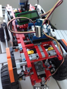
Lego 4x4 OffroaderFor the evenings at late summer holidays on a small island in the German north sea I bought a Lego 4×4 Offroader to build with the kids. The truck has 4×4 driving and steering, and is controlled by an ir remote. Coming home with the built truck  I was curious whether I could use an arduino to control the car.

So let’s share what I found out: The truck uses the Lego power functions (info). One could use wiring to control it, but since I got some experience with ir control, I tried it this way, so no physical connection is needed. I found three libraries out there to control Lego power functions with the arduino and ended with this one: LEGOPowerFunctions. To get it to run I had to insert the line “#include <Arduino.h> in the legopowerfunctions.h file. After that everything worked fine. Spending a lot of time with soldering in the last projects I also wanted to try a system without soldering, so I gave the grove system from seeed a try. For a small prove of concept I used an IR Emitter, a LCD Display (for debugging),  a LED-Bar and an ultrasonic range sensor. And here is the (simple) code which you can use as start. It simply drives the truck forward and backs up and turn if it is approaching  a wall. It also gives some simple debugging info on LCD and the LED-Bar.


define TRIGGER_PIN  2  //12  // Arduino pin tied to trigger pin on ping sensor.
#define ECHO_PIN     3  //11  // Arduino pin tied to echo pin on ping sensor.


#include <legopowerfunctions.h>

#include <SerialLCD.h>
#include <SoftwareSerial.h> //this is a must
#include "LED_Bar.h"

LED_Bar myLED;

// IR led on port 13
//LEGOPowerFunctions lego(13);
LEGOPowerFunctions lego(5);

int timeout, count;
unsigned long int distance;

SerialLCD slcd(6,7);//this is a must, assign soft serial pins

void setup()
{           

  myLED.set_LED_Index(0b000001101010101);
  //Ping
  pinMode(TRIGGER_PIN, OUTPUT);     
  pinMode(ECHO_PIN, INPUT);

  slcd.begin();
  // Print a message to the LCD.
  slcd.print("hello, world!");
  delay(3000);
}

void loop()
{
  while(1){

    distance = pingIt();  

    if (distance <= 40) {
      slcd.setCursor(0, 1);
      slcd.print("Rueckwaerts  ");
      lego.ComboPWM(PWM_FWD7, PWM_REV6, CH2); //
      delay(700);
    } 
    else
    {
      slcd.setCursor(0, 1);
      slcd.print("Forward  ");
      lego.ComboPWM(PWM_FLT, PWM_FWD6, CH2); //Forward 4WD
      delay(700);
    }  

  }

  slcd.setCursor(0, 1);
  slcd.print("PWM_FWD3  ");
  lego.ComboPWM(PWM_FLT, PWM_FWD3, CH2); //Forward 4WD
  pingIt();
  delay(3000);

  slcd.setCursor(0, 1);
  slcd.print("PWM_FWD4  ");
  lego.ComboPWM(PWM_FWD7, PWM_FWD4, CH2); //Forward 4WD
  pingIt();
  delay(1000);

  slcd.setCursor(0, 1);
  slcd.print("PWM_FWD5  ");
  lego.ComboPWM(PWM_REV7, PWM_FWD5, CH2); //Forward 4WD
  pingIt();
  delay(3000);

  slcd.setCursor(0, 1);
  slcd.print("PWM_FWD6  ");
  lego.ComboPWM(PWM_FLT, PWM_FWD6, CH2); //Forward 4WD
  pingIt();
  delay(3000);

  slcd.setCursor(0, 1);
  slcd.print("PWM_FWD7  ");
  lego.ComboPWM(PWM_FLT, PWM_FWD7, CH2); //Forward 4WD
  pingIt();
  delay(3000);

  slcd.setCursor(0, 1);
  slcd.print("ComboMode  ");
  lego.ComboMode(RED_FWD, BLUE_FWD, CH2);
  pingIt();
  delay(3000);

  // }

  slcd.setCursor(0, 1);
  slcd.print("zwei  ");  
  lego.ComboMode(PWM_FLT, PWM_FWD4, CH2); //Left Backward
  delay(3000);

  slcd.setCursor(0, 1);
  slcd.print("drei  ");
  lego.ComboMode(PWM_FLT, PWM_FWD7, CH2); //Left Forward
  delay(3000);

  slcd.setCursor(0, 1);
  slcd.print("vier   ");
  lego.ComboMode(PWM_FLT, PWM_BRK, CH2); //Right Forward
  delay(3000);

  slcd.setCursor(0, 1);
  slcd.print("fuenf  ");
  lego.ComboMode(PWM_FLT, PWM_REV4, CH2); // Right Backward Not Working
  delay(3000);

  slcd.setCursor(0, 1);
  slcd.print("sechs   ");

  lego.ComboMode(PWM_FLT, PWM_REV1, CH2); //Forward 4WD
  delay(3000);

  slcd.setCursor(0, 1);
  slcd.print("sieben   ");  
  lego.ComboMode(PWM_FLT, PWM_REV7, CH2); //Left Backward
  delay(3000);

  slcd.setCursor(0, 1);
  slcd.print("acht   ");
  lego.ComboMode(PWM_FWD2, PWM_FLT, CH2); //Left Forward
  delay(3000);

  slcd.setCursor(0, 1);
  slcd.print("neun   ");
  lego.ComboMode(PWM_REV4, PWM_FLT, CH2); //Right Forward
  delay(3000);

  slcd.setCursor(0, 1);
  slcd.print("zehn   ");
  lego.ComboMode(PWM_FWD3, PWM_FWD3, CH2); // Right Backward Not Working
  delay(3000);

  slcd.setCursor(0, 1);
  slcd.print("zehn   ");
  lego.ComboMode(PWM_FWD3, PWM_FWD3, CH2); // Right Backward Not Working
  delay(3000);

  /*

   timeout = 5; // 5 secs
   count = 0;
   while(timeout > 0)
   {
   //lego.ComboPWM(PWM_REV4, PWM_FWD4, CH2); // 50% speed
   lego.ComboPWM(PWM_FLT, PWM_FWD4, CH2); // 50% speed
   delay(100);

   if (count++ == 1)
   {
   timeout--;
   count = 0;
   }

   }
   lego.ComboPWM(PWM_FLT, PWM_FLT, CH2); // stop
   delay(1000);
   timeout = 3; // 5 secs
   count = 0;
   */
  /*
  while(timeout > 0)
   {
   lego.ComboMode(RED_FWD, BLUE_FWD, CH2);  // turn
   delay(100);
   if (count++ == 10)
   {
   timeout--;
   count = 0;
   }
   }
   */
}

long unsigned int pingIt(){
  // Start Ranging
  long unsigned int distance;
  int ii;

  digitalWrite(TRIGGER_PIN, LOW);
  delayMicroseconds(2);  //4 2
  digitalWrite(TRIGGER_PIN, HIGH);
  delayMicroseconds(10); //20 10  5
  digitalWrite(TRIGGER_PIN, LOW);
  // Compute distance
  distance = pulseIn(ECHO_PIN, HIGH);
  distance= distance/58;

  myLED.set_LED_Range(ledBarRange(distance));

  slcd.setCursor(0, 0);
  slcd.print("         ");

  slcd.setCursor(0, 0);
  slcd.print(distance, DEC);
  //lcd_print(0, "Ping");
  //lcd_print_special(turn, distance);
  //distanceLeds(distance);
  return distance;
}

int ledBarRange(long unsigned int aD){
  if (aD <= 5) return 10;
  if (aD <= 10) return 9;
  if (aD <= 15) return 8;
  if (aD <= 20) return 7;
  if (aD <= 30) return 6;
  if (aD <= 40) return 5;
  if (aD <= 50) return 4;
  if (aD <= 70) return 3;
  if (aD <= 90) return 2;
  return 1; 
}


iLOE for iPad, work in progress ….

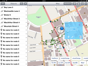
A pre alpha screenshot

Hard working on iLOE for iPad (OpenStreetMap editor for iPad). A little bit tired, finding out that it just takes time (and energy) to implement one usecase after the other.  Lost a few hours last night, just to find out that sending data with “DELETE” isn’t supported on most REST frameworks. (See here). Found a workaround today.

Pushing hard, cause I’ll visit a nearly (OpenStreetMap) unmapped area this week, so that’ll be perfect to give a test (and map) to the early alpha version. So what is finished by now? Having different (and switching) maps as background. Switching between official and test OSM server. Of cause login for both servers. Downloading nodes and ways. Adding, editing, moving and deleting nodes. Upload nodes to server. Changing markers on map. What’s open? Now it is all about ways: Creating, deleting ways; adding, sorting and deleting nodes. And, …, a lot of fixing. Stay tuned.

[Update: Just found out that there is a bug with core data: If you got ordered “To-many relations”, xcode creates NSOrderedSets for them. Problem is the created methods won’t work. What can one do? Implement all the stuff yourself. So copy the OrderedSet to a MutualOrderedSet. Do whatever. Pack the new Set to the persistance class and save. (see here)

For all of you wondering what I was writing about: I’m working on a tool to help OpenStreetMap to give Google Maps, Apple Maps and Microsoft Bing a little bit competition.

iOS: MKNetworkKit send XML (simple, easy, fast)

Maybe this is what you’re looking for: Easy sending some XML with MKNetworkKit.

This works for me:
MKNetworkOperation *op = [self operationWithPath:@”api/0.6/changeset/create” params: nil httpMethod:@”PUT”];
[op setCustomPostDataEncodingHandler: ^NSString *(NSDictionary *aD){return @”Put your XML here“;} forType:@”text/xml”];

That’s it

Die Pebble, Test und Tipps

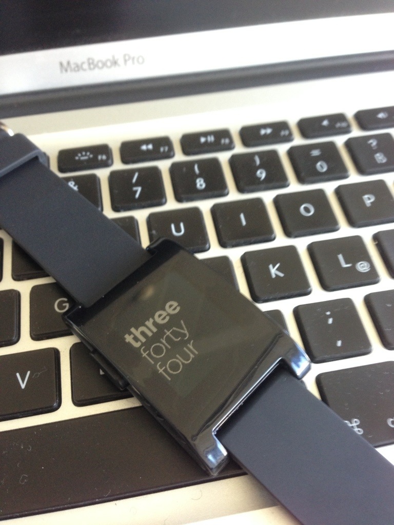
Nachdem ich letztens die Pebble vom Zoll in Garching (Münchner, oder zumindest ein Teil der Münchner dürfen dazu ins Umland fahren) abgeholt habe, hier ein kurzes Pebble Review. Getestet mit iOS 6 auf einem iPhone5

Installation: Problemlos, 9/10
Design Gehäuse: Mein Geschmack ist es nicht. Zuviel (alles?) Plastik. Aber ok, 5/10
Viel wichtiger, Funktion(en):
Grundfunktionen: SMS, iMessage, Anrufanzeige (Bug bei Namen mit length > 20 wird nur die Nr angezeigt), auser dem Bug: Einwandfrei 8/10. Musikfernsteuern: Titelanzeige, vor, zurück: Perfekt! Lautstärke wäre noch gut. Aber dafür fehlen schlichtweg weitere Tasten.
Erweiterte Funktionen: Mail funktioniert nur eine Weile. Die App. Lauert im Hintergrund auf Mails’ die sie aus dem Benachrichtigungsbildschirm abgreift. Das funktioniert eine Weile, aber irgendwann, scheinbar, räumt das OS im Hintergrund auf, dann geht die Verbindung verloren und kann nur manuell pro Mail Account wieder hergestellt werden (Notifications ein/aus). Allerdings bei mir auch nicht wirklich reproduzierbar. Schaut derzeit nach Voodoo aus …. warten wir mal auf ein Update. Seit ein paar Tagen steht jetzt endlich das erste Watch-SDK bereit und schon stehen die ersten Apps und vor allem inzwischen Dutzende Uhren/Zifferblätter zum Download bereit. Was noch aussteht ist das SDK auf iPhone (oder Android) Seite um eigene Informationen aus der eigenen App an die Pebble zu senden. Noch 2 Tipps zum Instalieren: Seiten der Watchface hier oder hier im iPhone Browser aufrufen, dort aussuchen. ->Download, damit startet die Pebble App die die neue App installiert. Uhren finden sich beim Durchblättern der Uhren, Apps jedoch im Menu der Pebble.

Achso was möchte ich eigentlich damit noch machen? Ein Mini-Navi, welches mindestens die richtige Richtung und Abstand zum Ziel anzeigt. Natürlich mit OSM (OpenStreetMap).

20130420-230134.jpg

Easy Arduino LED Clock

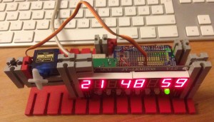
Arduino Clock in Fischertechnik

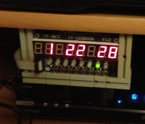
How to build an easy arduino clock. Why building a clock, since one can buy all kind of clocks? Two causes, first for the fun of it and second I can build the functions as I like and how they work. I also plan to add more functions from time to time.I wrote easy, that means not doing too much on the hardwork side. One can get an 8 7-segment LED (TM1638 LED Display Modules) with electronics, so there are only 5 wires needed for the display (and there are added 8 buttons).  5 more wires for the real time clock and off we go.

Another clock, with servo.

Wiring is an easy job, it’s explained in the source code. I implemented only settings for hour and minute (changing minutes also resets seconds), as I think it’s easier to set the date once with the arduino IDE. But feel free to add the extra functions.

I plan to add functions for servos and others for alarm and count down timer.

Here are the links which will help you: TM1638, Library DS1302

And here is the code:

/*
 Clock Program 2014
 by Johannes Eiseler eiseler.synology.me/wordpress
 given to public domain

shows time and date on a TM1638

use buttons for brightness, and setting hour and minute
// feel free for using it setting the date
// use the leds too


uses this libraries:
#include <TM1638.h>
#include <DS1302.h>
 
#include "Timer.h" // Use a timer


 */
 
 
#include <TM1638.h>
#include <DS1302.h>

#include "Timer.h" // To do it with a timer

 
// define a module on data pin 8, clock pin 9 and strobe pin 7
// am stecker: rot ist plus; dann in der reihenfolge: Vcc, Gnd, CLK, DIO, STB0
//TM1638 module(8, 9, 7); // data, clk, strobe

TM1638 module(8, 7, 9); // data, clk, strobe -> this is easer for wiring
 
// Init the DS1302
DS1302 rtc(2, 3, 4);
 
// DS1302: CE pin -> Arduino Digital 2 RST
// I/O pin -> Arduino Digital 3 DAT
// SCLK pin -> Arduino Digital 4 CLK
// VCC, GND, CLK, DAT, RST
 
Time time;
unsigned long timenumber;
String mystring = String(8);
int ss, ss1, dir;
int hh, mm;
byte bright = 3;
 
Timer timer;
byte mybyte;
// Status 0=zeit anzeigen
// --- erstmal nichteinstellen 1=Jahr, 2=Mon, 3=Tag, 4=DayOfWeek, 5=hh, 6=min, 
// einstellen 1=HH, 2=Min, 3=Sec 
int status = 0;
 
//Servos
 
void setup() {

// Serial.begin(9600);
 
 // Set the clock to run-mode, and disable the write protection
 rtc.halt(false);
 rtc.writeProtect(false);


 //#################################

 // The following lines can be commented out to use the values already stored in the DS1302
 // but comment in the first run
 /*
 rtc.setDOW(THURSDAY); // Set Day-of-Week to ....
 rtc.setTime(14, 40, 0); // Set the time to 12:00:00 (24hr format)
 rtc.setDate(25, 8, 2016); // Set the date to August 8th, 2016
*/

 //#################################

 
 // display a hexadecimal number and set the left 4 dots
 module.setDisplayToHexNumber(0x1234ABCD, 0xF0); //Test
 module.setupDisplay(true, 1);
 
 //Serial.begin(9600);
 
 timenumber = 123456;
 //Serial.begin(9600); // zum debuggen
 mybyte = 1;
 // Uhrzeit im RTC-Chip setzen nur einmal
 //RTC.setTime(&time);
 
 ss= 0;
 ss1=0;
 dir = 0; // Lauflicht Richtung
 
 
 timer.every(125, doTick);
 
}
 
void loop() {
 
 timer.update();
 
 byte keys = module.getButtons();
 
 switch(keys){
 case 0b0000001: //leftmost button
 bright++; 
 if (bright >8) bright = 0;
 module.setupDisplay(true, bright);
 //module.setLEDs(0b10101010 & 0x00FF);
 module.setLEDs(bright & 0x00FF);
 delay(500);
 
 break;
 case 0b0000010: //leftmost + 1button Start setting
 status ++;
 if (status == 3) status = 0;
 delay(500);
 break;
 case 0b0000100: //leftmost + 2button plus hh oder min
 if (status == 1) {
 hh++;
 if (hh >= 24) hh = 0;
 rtc.setTime(hh, mm, 0);
 }
 if (status == 2) {
 mm++;
 if (mm >= 60) mm = 0;
 rtc.setTime(hh, mm, 0);
 }
 delay(250);
 break;
 case 0b0001000: //leftmost + 3button minus hh oder min
 if (status == 1) {
 hh--;
 if (hh < 0) hh = 23;
 rtc.setTime(hh, mm, 0);
 }
 if (status == 2) {
 mm--;
 if (mm < 0) mm = 59;
 rtc.setTime(hh, mm, 0);
 }
 delay(250);
 break;
 }
 
 delay(10);
 
}
 
void doTick(){
 
 // light the first 4 red LEDs and the last 4 green LEDs as the buttons are pressed
 // module.setLEDs(((keys & 0xF0) << 8) | (keys & 0xF));
 // hin und her lauflicht
 if (status < 1) {
 if (dir == 0) mybyte = mybyte << 1;
 else mybyte = mybyte >> 1;
 module.setLEDs(mybyte & 0x00FF);
 if (mybyte == 1) dir =0;
 if (mybyte ==128) dir = 1;
 } 
 else {
 //module.setLEDs(0b11111111 & 0xFF00); 
 module.setLEDs(0xFF00); //alle rot
 //module.setLEDs(0x00FF); //alle grün 
 }
 // ende lauflicht
 
 //RTC.getTime(&time);
 time = rtc.getTime();
 
 //Serial.println(time.sec);


// my rtc seems to be buggy, so next lines to clean
 if (time.sec == 0 && time.min == 0 && time.hour == 0) { delay(10); time = rtc.getTime(); };
 if (time.sec == 0 && time.min == 0 && time.hour == 0) { delay(10); time = rtc.getTime(); };
 if (time.sec == 0 && time.min == 0 && time.hour == 0) { delay(10); time = rtc.getTime(); };
if (time.sec == 0 && time.min == 0 && time.hour == 0) return;

 
 //ss1 = time.getSecond();
 ss1 = time.sec;
 
 if (status < 1) {
 if (ss1 != ss){ //do nothing if the seconds didn't change since last display 
 word decpoints = 0b00000000;
 
 if ((ss1 >= 20 && ss1 < 24) || (ss1 >= 40 && ss1 < 44)){
 mystring ="";
 int dd = time.date;
 if (dd < 10) mystring = mystring +" ";
 mystring = mystring + String(dd);
 int mo = time.mon;
 if (mo < 10) mystring = mystring +"0";
 mystring = mystring + String(mo);
 int yy = time.year;
 mystring = mystring + String(yy);
 decpoints = 0b01010000;
 //if (ss1 < 26) servo1.write(45);
 //if (ss1 > 39) servo1.write(135);
 
 }
 else {
 
 ss = ss1;
 //timenumber = time.getHour() * 1000;
 timenumber = time.hour * 1000;
 mystring = "";
 hh = time.hour;
 if (hh < 10) mystring = mystring +" ";
 mystring = mystring + String(hh);
 mystring = mystring +" ";
 mm = time.min;
 if (mm < 10) mystring = mystring +"0";
 mystring = mystring + String(mm);
 mystring = mystring +" ";
 //ss = time.getSecond();
 if (ss < 10) mystring = mystring +"0";
 mystring = mystring + String(ss);
 }
 
 module.setDisplayToString(mystring,decpoints);
 }
 }
 else //button to set the time
 {
 hh = time.hour;
 mm = time.min;
 
 switch(status) {
 case 1: 
 mystring = "Hour" + String(hh) + " ";
 module.setDisplayToString(mystring,0);
 break;
 case 2: 
 mystring = "Min " + String(mm) + " ";
 module.setDisplayToString(mystring,0);
 break;
 }
 }
 
}

Raspberry Pi (Auch für Dummies)

Nackter Raspberry

Hat ein wenig gedauert bis ich welche hatte. Aber das Warten hat sich gelohnt (auch weil die Software inzwischen reifte 🙂 ).

Was ist es? Ein Minicomputer, etwas größer als eine Kreditkarte, mit 2 USB Anschlüssen, Audio out, Video out und HDMI (=DVI) Ausgang. Zusammen mit einer SD-Karte und einem Netzteil wird ein Linux Rechner daraus.

Vorab, für die Ungeduldigen, schon mal meine Bewertung: 8/10!

Wow, ich bin begeistert. Ein wirklich schönes Gadget. Kurz, was ich bisher ausgetestet bzw. gebaut habe:

  • XMBC (Eine Art Apple TV für Linux, Videos, Musik abspielen, Internetradio, YouTube, ARD-Mediathek, usw.) (bisschen Einstellungen suchen nach Installation).
  • Wetter Monitor in unserem Flur (läuft jetzt seit ca. 2 Wochen ohne Mucken. Hardware siehe unten) (bisschen Einstellung notwendig).
  • MAME (Emulator für alte Spiele) (Hmm, die Hälfte der getesten ROMs liefen).
  • MPD (MusicPlayerDaemon; Spielt mp3s und Internetradio ab) (bisschen Einstellung notwendig)
  • Zur Ergänzung des Wettermonitors, sonst idelt der ja nur: LAMP installiert und darauf dann noch Joomla (ein CMS) (easy)
  • Und weil es immer noch performt und Google den Reader abschalten will: Noch TinyTinyRSS (heise Anleitung) mit der mobile Erweiterung

Was sollte man haben (KnowHow und Hardware)?

Ein paar UNIX Basics wären schon nicht schlecht, oder man lernt sie dabei. Nein, man muss nicht Löten können. USB-Stecker richtig rum reinstecken reicht. Ich empfehle folgende Hardware:

  • Den Paspberry Pi
  • Ein paar (2 oder mehr) SD Karten (>=4 GB) (Jede Karte ein eigener Rechner 🙂 )
  • Eine Stromversorgung (5V, 1A) bzw. einfacher..
  • … gleich ein aktives USB-Hub mit mindestens 1A (möglichst kein Ramsch). Versorgt gleichzeitig den Raspberry.
  • Ein HDMI auf DVI Adapter (damit man (am Anfang) auch mit dem Monitor testen kann. Oder ein HDMI Kabel wenn man (nur) an den fernseher will. Später reicht übrigens auch ssh, also rein remote.
  • Tastatur und Maus. Später reicht ssh
  • Ein USB WLAN Dongle (wenn man weg vom eingebauten Ethernetanschluss will)
  • Wer möchte auch noch ein Gehäuse dazu.

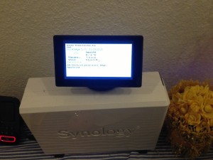
Wetter Station

Die links ergänze ich Euch noch zusätzlich. Und im nächsten Blog,  Mini HowTos. Stay tuned.

Arduino – Crash Kurs für IT’ler

Es gibt bereits viele Anleitungen für den Arduino, hier ein Crashkurs für Leute aus dem  IT-Umfeld.

Was ist es?

EIn Platine um eigene Hardware bauen zu können. Programmiersprache ist (fast) C; die Hardware ist so abstrahiert, dass (fast) keine Elektronikkenntnisse erforderlich sind. Arduino ist ähnlich Lego NXT oder Fischertechnik Computing, aber offener und günstiger. Programme werden Sketch genannt (warum auch immer), (aufsteckbare) Zusatzhardware nennt sich Shield.

Was kann es?

Anwendungsbeispiele was man machen kann: Von blinkenden Leuchtdioden, Uhren, Messfühler auswerten, Webserver bis Robotern geht alles. Eingänge gibt es digital und analog, Ausgänge digital und pwm (Pulsweiten moduliert). D.h. kleine Verbraucher (LEDs) kann man (mit Vorwiderstand) direkt anschliessen. Besonders cool sind die PWM Ausgänge. damit kann man direkt Modellbauservos ansteuern. Der Arduino ist ziemlich robust, d.h. man kriegt ihn nur mit viel Pech kaputt.

Wie geht es und was brauche ich?

Arduino Uno, ein Steckbrett, Kabel und ein paar LEDs (am besten die mit Vorwiderstand für 5V) kaufen. Alternativ ein Einsteigerset. Arduinosoftware installieren, Arduino mit 1 LED verkabeln.  Und los geht’s. Wenn’s Spaß macht dabei bleiben, ansonsten waren die Kosten bisher überschaubar.

(Von mir ausprobierte) Bezugsquellen:

Watterot (Arduino und Co.), Reichelt (allgemein Elektronik, z.B. die LEDs), Dealextreme (billig, aber 2-6 Wochen Lieferzeit, achtung Zoll wenn > 20€, einzeln bestellen (ohne Versandkosten))

Tipps und Tricks

Für Motoren (für Roboter, Lego, Fischertechnik) benötigt man ein Motor Shield, Entfernungen messen, Suchwort ping, günstig über ebay.